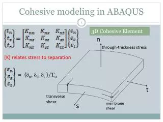
Introduction to ABAQUS
Introduction to ABAQUS. 27 th February, 2007. Units. Before starting to define any model, you need to decide which system of units you will use. ABAQUS has no built-in system of units. . Material Properties General properties: ρ =7800kg/m 3 Elastic Properties E=200x10 9 v =0.3

Introduction to ABAQUS
E N D
Presentation Transcript
Introduction to ABAQUS 27th February, 2007
Units • Before starting to define any model, you need to decide which system of units you will use. ABAQUS has no built-in system of units.
Material Properties General properties: ρ=7800kg/m3 Elastic Properties E=200x109 v=0.3 All members are circular steel rods, 5mm in diameter Example -a model of an overhead hoist
Procedure • Sketch the two-dimensional geometry and create a part representing the frame • Define the material properties and section properties of the frame • Assemble the model • Configure the analysis procedure and output requests • Apply loads and boundary conditions to the frame • Mesh the frame • Create a job and submit it for analysis • View the results of the analysis
Creating Part • start ABAQUS/CAE • Create Model Database from the Start Session • In the Model Tree, double-click the Parts • Name the part Frame. Choose a two-dimensional planar deformable body and a wire base feature • In the Approximate size text field, type 4.0 • ABAQUS/CAE automatically enters the Sketcher. The Sketcher contains a set of basic tools that allow you to sketch the two-dimensional profile of your part
Creating Part • Select Rectangle toolto draw a rectangle • Select the Delete tool > choose Constraints >Using [Shift]+Click, select the four perpendicular constraints and delete them (press Done) • Use the Add Constraint tool to constrain the top and bottom edges so they remain parallel to each other • Use the Add Dimension tool to dimension the edges of the rectangle
Creating Parts Now sketch the interior edges of the frame: • Use the Connected tool to start the first line at the upper-left corner of the sketch and extend it to any point that snaps onto the bottom edge and continue the second line to the upper-right corner • Use the Split tool to split the bottom edge at the point where it intersects the two lines by selecting the bottom edge as the first entity to define the split point and select either of the two interior lines as the second entity • Add Constraint tool to constrain the two segments of the bottom edge so they are of equal length To complete the sketch, click Done to exit the Sketcher From the main menu bar, select File Save
Creating a material • To define a material: • In the Model Tree, double-click the Materials container to create a new material • Name the material Steel • In the menu bar, choose MechanicalElasticityElastic • Type a value of 200.0E9 for Young's modulus and a value of 0.3 for Poisson's ratio in the respective fields
Defining and assigning section properties • The section properties of a model is defined by creating sections in the Property module To define a truss section -requires only a material reference and the cross-sectional area • Choose Sections to create a section. • Name the section FrameSection > select Beam in the Category list >select Truss in the Type list • select Steel for the Material • In the Cross-sectional area field, enter a value of 1.963E-5 To assign the section to the frame: • Under Parts ,expand the Frame item • Double-click Section Assignments > highlights the entire frame >click Done in the prompt area to assign the frame to section
Defining the assembly define the geometry of the assembly by creating instances of a part and then positioning the instances relative to each other in a global coordinate system To define the assembly: • Click Assembly under the Module list > double-click Instances • select Frame
Configuring your analysis • To create a static, general analysis step • double-click the Steps • Change the step name to Apply load • Select Static, general • In the Description field, type 10 kN central load • Requesting data output Once you create a step, ABAQUS/CAE generates a default output request for the step
Applying boundary condition Prescribed conditions, such as loads and boundary conditions, are step dependent, which means that you must specify the step or steps in which they become active Define BC at left end • In the Model Tree, double-click the BCs container. • Name the boundary condition Fixed • select Initial as the step in which the boundary condition will be activated. All the mechanical boundary conditions specified in the Initial step must have zero magnitudes • Choose Mechanical > select Displacement/Rotation, and click Continue • select the vertex at the bottom-left corner of the frame • Toggle on U1 and U2 since all translational degrees of freedom need to be constrained
Applying boundary condition and load Define B.C at the right end • Repeat the above procedure to constrain degree of freedom U2 at the vertex at the bottom-right corner of the frame. Name this boundary condition Roller Applying a load to the frame • Double click load • Name the load Force • From the list of steps, select Apply load • Choose Mechanical > Concentrated force • select the vertex at the bottom center of the frame as the region where the load will be applied • Enter a magnitude of -10000.0 for CF2
Meshing the model • To assign an ABAQUS element type • double-click Mesh • From the main menu bar, select Mesh > Element Type. • selects the entire frame as the region to be assigned an element type • In the dialog box, select the following: • Standard as the Element Library selection (the default). • Linear as the Geometric Order (the default). • Truss as the Family of elements.
Meshing the model • Basic meshing is a two-stage operation: first you seed the edges of the part instance, and then you mesh the part instance To seed and mesh the model: • Seed > Part to seed the part instance. • specify an approximate global element size of 1.0 • Mesh > Part to mesh the part instance display the node and element numbers • View > Part Display Options >Toggle on Show node labels and Show element labels
Creating an analysis job To create an analysis job • double-click the Jobs • Name the job Frame • In the Description field, type Two-dimensional overhead hoist frame • Submit the job
Postprocessing with ABAQUS/CAE Displaying and customizing a deformed shape plot • Plot Deformed Shape; or use the tool in the toolbox To display node and element numbers: • select Options > Common; or use the tool in the toolbox. • The Common Plot Options dialog box appears. • Click the Labels tab. • Toggle on Show node labels and show element labels
Postprocessing with ABAQUS/CAE To generate field data reports • select Report Field Output • Integration Point>Click the triangle next to S: Stress components > S11. • In the Setup tabbed page, name the report Frame.rpt • The element stresses are written to the report file • change the position to Unique Nodal in the Report Field Output dialog box • Toggle off S: Stress components, and select U1 and U2 from the list of available U: Spatial displacement variable • toggle off U: Spatial displacement, and select RF1 and RF2 from the list of available RF: Reaction force variables