TELECOMMUNICATION
TELECOMMUNICATION. ENG. Mohammed Samsher Ali. FIBER OPTIC (FLAG) . A universal carrier of gigabit Information for all utilities. A universal carrier of gigabit information for all utilities. FIBER OPTIC (FLAG). Mohammed Samsher Ali Senior consulting Engineer (Communication)

TELECOMMUNICATION
E N D
Presentation Transcript
TELECOMMUNICATION ENG. Mohammed Samsher Ali
FIBER OPTIC (FLAG) A universal carrier of gigabit Information for all utilities
A universal carrier of gigabit information for all utilities FIBER OPTIC (FLAG) Mohammed Samsher Ali Senior consulting Engineer (Communication) Zuhair Fayez Partnership Consultant
Introduction PAPER OUTLINE Fiber Optic Communication FLAG (Fiber Optic Link Around the Globe) Communication need of Private / Public utilities FLAG Integration scheme for all utilities SPECIAL REFERENCE TO SCECO/SEC
WIRE COMMUNICATION COMMUNICATION MEDIA COPPER CABLE FIBER OPTIC CABLE SUBMARINE CABLE POWER LINE WIRELESS COMMUNICATION H.F / VHF / UHF MW / SATELLITE / SHF
STANDARD FCC ALLOCATION VLF/LF/MF/HF/VHF/UHF/SHF/ehf (Radio-MW, SW, VHF Radio, TV, Cellular (GSM), Mobile and Fixed Satellite, Millimeter Radio Distribution) NEED FOR HIGHER BANDWIDTH High Speed LAN, Real Time Video, High Definition TV, Multimedia, FREQUENCY SPECTRUM
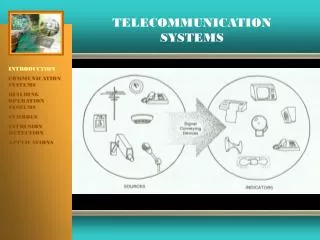
INTRODUCTION FIBER OPTIC COMMUNICATIONSYSTEM TRANSMITTER Encoder, Optical Transmitter RECEIVER Optical Receiver, Decoder REPEATERS Invention of LASER in 1960, TYPES OF FIBER Mono-mode, Multi-mode, Step Index, Graded Index
ADVANTAGES FIBER OPTIC COMMUNICATIONSYSTEM • Very Large Information Bandwidth • High Immunity to Interference • Negligible Cross Talk • Completely Electrical Isolation • No FCC Regulation, No Need of Licensing • Excellent Mode for Digital Transmission • No easy to tap or eavesdrop • Larger Repeater Spacing • Light weight, Cheaper, Flexible ease of Handling • Non Reactive to Nuclear Radiation • Cabling possible along the same transmission Line • Longer Life Expectancy.
DISADVANTAGES FIBER OPTIC COMMUNICATIONSYSTEM • Were related to Repeaters, • Connectors, Splicing etc. • Now - Hardly Anything to name.
BASIC NEED ADMINISTRATIVE ,OPERATIONAL , CURRENT SCENARIO(High Bandwidth Demand) COMMUNICATION NEED OF ALL UTILITIES ORGANIZATIONS LIKE POWER(SCECO/SEC),OIL(SAUDI ARAMCO) BANK (NCB, SBB, RB etc.) MEDIUMS USED EXCLUSIVE (HF ,VHF ,MW ,SAT ,F.O ETC) LEASED / DDN - PTT or PUBLIC AGENCIES
BASIC CONCEPT Since 1920 used by US power utilities Voice ,Protective relaying , Telemetering ,Load Dispatching Power Sector Communication SELECTION CRITERIA PLCC is the backbone Judicious mix of Digital Microwave and Fiber Optic Communication Satellite Communication Leased Lines from PTT
PLC COMPONENTSTerminal Equipment (Tx ,Rx ,Associated Components) Coupling Equipment (WT ,CC ,LMU ,) High Voltage System( T.L ,S/S ,Control Centers) ADVANTAGES / DISADVANTAGES Advantages - Reliable ,Cheapest ,Controlled by user not by third party,No FCC licensing ,Versatile and Viable Disadvantages - Limited frequency (50 - 500 kHz) ,Bandwidth Limitation ,Susceptible to impulse noise ,Interference ,Sensitive to climatic variations POWER SECTOR COMMUNICATION
FIBER GENERATION 1st Generation-850nm, Graded Index, used for Inter-City 2nd Generation(in 1983)- 1330n, Mono-mode with Higher BW and Lower Attenuation. 3rd Generation (in 1989)- 1550nm, Dispersion Shifted Fiber FIBER OPTIC COMMUNICATION IN POWER UTILITIES CABLE TYPES and INSTALLATION OPGW (Optical Fiber incorporated in the Ground Wire) WA ( Optical Fiber Cable Wrapped Around the Ground Wire) MFSS (Metal Free Self Supporting)
FUTURE TRENDS Advancement in Optical Amplifier,Solid State LASER Diodes with antireflection Coating, Erbium Doped Optical Amplifiers for 1550nm,Using G.653 DSF Repeaters FOPU Advantage Over the Cable/Co-axial cable medium. ADVANTAGES All Advantages of Fiber Optic Communication Cheaper, Reliable, Dedicated and Secured.
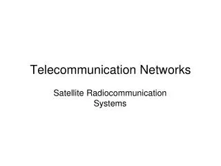
INTRODUCTION Ancient Origin, Copper Telephone Cables / Co-axial Cables GENERATION SEA - ME - WE(South-East Asia, Middle East, Western Europe-1) Started in June 1986, the SEA-ME-WE-2 and now SEA-ME-WE-3, with 36,000Km, 40 Landing Points. FOG(Fiber Optic Gulf)- 1300Km, Submarine F.O. Cable, 5 Gbits, for Kuwait, Bahrain, Qatar and UAE. FLAG( Fiber Optic Link Around the Globe) PROJECT OXYGEN ( Recent Origin) SUBMARINE CABLES
EXISTING TREND Analog to Digital, Narrow Band to Wide Band SDH,ISDN and ATM Frame Relay to Gigabit Ethernet Voice over Data Video Conferencing Internet/Intranet Optical Amplification WDM to Dense WDM FLAG
CAPABILITIES Spans 3 Continents, Links 12 Countries Boasts 28,000Km, 1,20,000Circuits of 64Kbps 6,00,000 simultaneous Conversations in each segment, Based on SDH 14 Landing Points in Middle East New Segments have 32Gbps over each Fiber Pair Majority users are ISPs FLAG
FUTURE PROJECTS Named as PROJECT OXYGEN Planned for 1,53,000Km in Submarine F.O 78 Countries, 98 Landing Points, ATM Architecture with ITU Digital Standard Traffic flow 640 Gbps capacity on each circuit Customer can purchase/Hire/resale the capacity Completion of Phase 1 by end of 2003. FLAG
BASIC CONCEPT High - Speed, ultra-high capacity Optical Fiber Network Capable of Transmitting (Audio, Text and video Signal ) BROAD BAND ADVANTAGES INFORMATION SUPERHIGHWAY
PREFERENCE FOR MEDIUM PREFERABLY Optical Fiber
PHILOSOPHY OF INTEGRATION INTEGRATION TECHNIQUE
POWER SUB STATION WITH RTU, COUPLINGEQUIPMENT POWER SUB STATION WITH RTU,COUPLINGEQUIPMENT I N T E R F A C E M O D UL E M U L T I P L E X E R L I N E T E R M I N A L EQPT. O P G W/ WA / KUWAIT O P G W /WA / D PR/RTU I N T E R F A C E M O D U L E L I N E T E R M I N A L EQPT. M U L T I P L E X E R D PR/RTU D SCADA SCECO/ SEC D SCADA POWER UTILITY FROM GENERATION OR DISTRIBUTIONCENTRE A SCECO/ SEC VOICE/DATA A MFSS MFSS VOICE/DATA D COMPUTER D COMPUTER A VFT A VFT A PABX A PABX D JEDDAH SUDAN ISDN D “LANDING POINT FOR SAUDI ARABIA” ISDN A A STC ANY AGENCY PABX FLAG D D LEASED PUBLIC USE FIBRE OPTIC COMMUNICATIONS INTERFACES STATION “B” FIBRE OPTIC COMMUNICATIONS INTERFACES STATION “A” PABX ERITRA ADEN PTT / STC ETHIOPIA LEGEND: FIBRE OPTIC OPGW/WA/,MFSS /CABLE FLAG CABLE FIG.2 : PROPOSED SCHEME FOR INTEGRATING POWER UTILITY COMMUNICATION SYSTEM WITH PRIVATE / PUBLIC UTILITIES. SEA-ME-WE CABLE PROPOSED SCHEME
ADVANTAGES Optimum Utilization of the Medium Leasing / Sharing Very High BW available for all users Ultramodern Communication Facilities at door step Reliable, Secured Better S/N Ratio Cost Effective MAJOR BENEFITS
CONCLUSION Change Your Services Before Somebody forces you To do so