3 H +
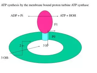
ATP synthesis by the membrane bound proton turbine ATP synthase. ADP + Pi. ATP + HOH. F1. F0. 2 e-. 3 H +. 3 OH-. Proton pump, same efficiency in ATP synthesis and hydrolysis

3 H +
E N D
Presentation Transcript
ATP synthesis by the membrane bound proton turbine ATP synthase ADP + Pi ATP + HOH F1 F0 2 e- 3 H+ 3 OH-
Proton pump, same efficiency in ATP synthesis and hydrolysis Coupling membrane conserve the DmH+ formed by pumping of H+ by the electron transport chain in the membrane during oxidation. DmH+ is used for ATP synthesis by the pump. Mechano-electric process of the turbine convert DmH+ to chemical bond. 3H+/ATP , Mg++, cofactor, no acylphosphate intermediate.
F1- catalytic sector, 5 subunits: 3a, 3b, g, d, e, 400 kD F0 - membrane sector, 3 subunits: a, 2b, 9c, 150 kD 6 ATP binding site one on each of the a and b subunits The 3 active sites are on the 3b subunits
MF1 (DCCD) a: red b: yellow g: blue e: magenta d: green 1E79 (pdb)
EF1Fo a: cyan b: pink g: MF1 red, EF1 green e: yellow c: orange
O O O O- O O O- AR-O-P-O-P-O- P-OH AR-O-P-O-P-O-P-O- O- O- O- H O- O- O- OH H Mg++ O O Mg++ O O C Glu 188 C Glu 188 ADP Pi Pentacovalent intermediate. O O O- ATP AR-O-P-O-P-O-P-O- O- O- O- H-O-H Mg++ O O- C Glu 188
Mode of action of catalysis Mg++ induces more positive P Nucleophylic attack by O- of ADP on the electrophyl P in Pi Formation of pentacovalent P as a transition state intermediate in the formation of ATP OH- leaving group facilitated by general acid/base catalysis of Glu188 ADP-VO5 transition state inhibitor F1-bound ADP-VO5 is trigonal bipyramide pentacoordinate vanadium Km(Pi) 500 mM Km(Vi) 500 mM Ki(ADPVi) 12.4 mM Kd(ADPVi) 0.5 nM
Binding-Change mechanism ADP Pi ATP ATP g ADP Pi ADP Pi ADP Pi DmH+ ATP HOH ATP ADP Pi ADP Pi ADP Pi ATP
Binding-Change rotation mechanism Each site sequentially participate in catalysis, 3 strokes for a full cycle Negative cooperativity in ATP binding between the 3 sites transmitted by the g subunit ATP tightly bind to one site. Keq = 1 of tightly bound ATP - ADP Pi Therefore energy is not needed for formation of unhydride bond in the formation of ATP Energy in a form of conformational change is needed for release of tightly bound products DmH is transmitted indirectly by the g subunit. It forms a shaft that is connected to the turbine in the membrane causing conformational changes in the three active sites during rotation.
Evidence for the hypothesis Single site KmATP =1.5x10⁻¹² M, V=1x10⁻³ s-1, DG= 0 Kcal/mole 3 sites KmATP =1.0x10⁻³ M, V=1x10³ s-1, DG= -12 Kcal/mole Km- low for single site because of tight binding of ATP but high to three sites due to negative cooperativty V- slow in single site mode because of slow release of ADP but fast in 3 sites mode Keq=1 from analysis of the concentrations of bound ATP, ADP and Pi at a single site Asymmetry in structure of the three active sites as seen from crystallography, empty, bound ATP and bound ADP Different interactions between g and each of the three b subunites
ATP Synthase1. F1 catalytic sector2. Fo membrane proton turbine 1bmf (PDB)
bTP (bound ATP) bE (empty)
g subunit bDP: b- active site subunit +ADP
E188 HOH T163 Mg ATP active site
Proton turbine Rotor- 9 c subunits arranged in a ring, each has two transmembrane hilexes single an essential Asp61 in the middle of the membrane Stator- one a subunit in the membrane, an essential Agr210, is attached to F1 by two extended b subunits. Shaft- g subunit attached to c with the aid of d and e, extended through a tunnel opened in the middle of F1. Transmit the rotation of the turbine to the catalytic subunits causing conformational changes. Arg 210 in a subunit has permanent + charge (high pKa) located between two Asp61 in c. Synthesis: H+ come through the half channel protonat unchanged Asp61- The protonated AspH is repulsed by Arg+ counter clockwise into the lipid. Protonated AspH approach Arg+. The + charge lower the pKa and deprotonate Asp. The proton move out through the half channel.
Arg+210 Asp61
Rotation Histage engineered at the n-terminal of b subunits in complex with a and g attached to glass slide coated with Ni-nitriloacetate. At the tip g-S107C mutated, linked to biotin-maleimide, avidin attach to C107 and flourescence biotintelated 2 mm actin filament is attached to the avidin on the g. Movement recorded by CCD vidio camera only when ATP added, NaN3 inhibited. F1 10 nm g 1 nm ATPase rate 52 s-1 (17 RPS) Rotaion 4 RPS (load) Torque 40 pN nm-1
Nickel dots array. Two methods, electron beam (e-beam) and nanoimprint lithography, were used to create nanofabricated substrates capable of precisely and accurately positioning individual biological motors. In the first method, a standard silicon wafer was coated with two layers of electron beam-sensitive polymer poly(methyl methacrylate) (PMMA) resist, with the lower layer being slightly more sensitive to the e-beam exposure. Arrays were patterned into the bilayer using e-beam lithography, followed by development. A 5 nm tantalum (Ta) adhesion layer and a 10 nm metallic nickel (Ni2+) layer were deposited using electron-beam physical vapor deposition. Lift-off was performed using a 1:1 solution of methylene chloride:acetone for 15 min followed by ultrasonic agitation for 10 s. Regular arrays of 60-600 nm size dots on 1 m pitch with circular profiles were confirmed by scanning electron microscopy. Arrays were stored under appropriate conditions (e.g., vacuum) to prevent oxidation of the Ni surface prior to experimental use.
Figure 1 Schematic diagram (A) and CCD photomicrograph (B) of fluorescent microspheres attached to the subunit of individual F1-ATPase molecules immobilized on nickel dot arrays(C) that were created using electron beam lithography. Dots are 50-250 nm diameter, 5-15 nm high.
Fig. 1. Schematic diagram of the F1-ATPase biomolecular motor-powered nanomechanical device. The device consisted of (A) a Ni post (height 200 nm, diameter 80 nm), (B) the F1-ATPase biomolecular motor, and (C) a nanopropeller (length 750 to 1400 nm, diameter 150 nm). The device (D) was assembled using sequential additions of individual components and differential attachment chemistries. Nickel propellers were made by lithography. The Ni was coated by biotinylated His rich peptide. The biotin attached to avidin connected to biotinylated g subunit of F1. His tag F1 was attached to Ni posts on the slide.
Fig. 2. Image sequence (viewed left to right) of nanopropellers being rotated anticlockwise at 8.3 rps (A) and 7.7 rps (B) by the F1-ATPase biomolecular motor. Observations were made using 100x oil immersion or 60x water immersion and were captured with a CCD video camera (frame rate 30 Hz). The rotational velocity ranged from ~0.8 to 8.3 rps, depending on propeller length. Data were recorded for up to 30 min; however, propellers rotated for almost 2.5 hours while ATP was maintained in the flow cell
Fig. 3. Time course of F1-ATPase subunit rotation. Each line represents data from a rotating nanopropeller. Solid lines, propellers 750 nm long; dashed lines, propellers 1400 nm long; dotted lines, propellers 1400 nm long in the presence of NaN3


![[SO 2 + H 2 O H 2 SO 3 ] SO 3 + H 2 O H 2 SO 4 CO 2 +H 2 O H 2 CO 3](https://cdn2.slideserve.com/4275035/slide1-dt.jpg)