Presentation Topic : Welding
Group : 1 Group Members Muhammad Summair Hariss Bin Waheed Mohsin Mumtaz Jahanzeb Qdeeir Khaqan Asad Kashif Amin. Presentation Topic : Welding. What is Welding

Presentation Topic : Welding
E N D
Presentation Transcript
Group : 1 Group MembersMuhammad SummairHariss Bin Waheed Mohsin MumtazJahanzeb QdeeirKhaqan AsadKashif Amin Presentation Topic : Welding
What is Welding Join together (metal parts) by heating the surfaces to the point of melting with a blowpipe, electric arc, or other means, and uniting them by pressing, hammering, etc
Welding Parts are joined together by Fusion. Fusion is brought about by a combination of heat and pressure between parts being joined. In normal welding processes very high temperatures and little or no pressure is used. • Welding conditions • Smooth joint surfaces that match each other • Surfaces clean and free from oxides, grease and dirt. • Metals to be joined have same microstructure
The metals should be good quality (no internal impurities) • Welding Preparation • Before starting a weld, the joint edges should be carefully prepared. • Beveling large edges • Cleaning (Chemical/Mechanical) Weld Joints Welding Symboles Welding Techniques
Weld Joints - Parts of a Weld Joint • Joint root • Groove face, Root face and Root edge • Root opening and Bevel • Bevel angle, Groove angle and Groove radius Weld Joints - Types of Weld Joint • Butt Joint • Lap Joint • T Joint • Corner joint • Edge Joint • Splice Member
Joint Root is that portion of a joint to be welded where the members are closest to each other • The joint root may be either a point, line, or an area • The joint roots are shown as shaded areas in (A)-(D) and lines in (E) (F)
Groove face, Root face and Root edge • Groove face is “ that surface of a member included in the groove” • Root face (land) is “that portion of the groove face within the joint root” • Root edge is a root face of zero width
Root opening and Bevel • Root opening is the separation between the work pieces at the joint root • Bevel (chamfer) is an angular edge preparation
Welding Joints Butt Joint A joint between two members aligned approximately in the same plane
Lap Joint A joint between two overlapping members
T Joint A joint between two members located approximately at right angles to each other
Corner Joint A joint between two members located at right angles to each other
Edge Joint A joint between the edges of two or more parallel or nearly parallel members
Splice member is “ the work piece that spans the joint in a spliced joint Single-spliced butt joint Double-spliced butt joint with joint filler
Basic components of awelding symbol Reference Line (Required element) Arrow Tail Reference Line must always be horizontal, Arrow points to the line or lines on drawing which clearly identify the proposed joint or weld area.
Weld Symbol Terminology OTHER SIDE Work ARROW SIDE Fillet Weld (Arrow Side Only) Fillet Weld (Both sides)
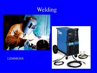
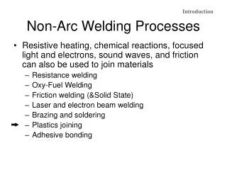
Welding Techniques • There are many different methods of welding. The difference between them is outlined by two important features • The way the metal is heated • The way additional filler metal if any is fed into the weld • Types of Welding • Electric arc welding • Gas Welding • Resistance Welding • Friction Welding • Robotic Welding
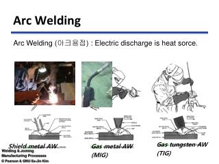
Electric Arc Welding The heat for fusion is supplied by an electric arc Arc is formed between electrode and work this melts and fuses the joint edges
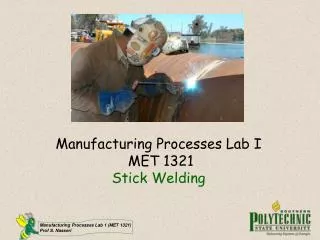
Manual Metal Arc (MMA) • Most widely used of all the arc welding processes • Commonly called “stick” welding Applications repair work, structural steelwork,
Electric Arc welding Electrode • In arc welding an electrode is used to conduct current through a workpiece to fuse two pieces together.,
The Electrode and Coating • Coating is a combination of chemicals • Cellulosic electrodes contain cellulose • Rutile electrodes titanium oxide (rutile) • Basic electrodes contain calcium carbonate (limestone) and calcium fluoride (fluorspar)
Advantages of Electric arc welding • Used with many electrode types & sizes • Used in all positions • Used on great variety of materials • Flexibility in operator control makes it the most versatile of all weldingprocesses • Low cost of equipment Dis-advantages • Rod becomes shorter & periodically needs replacing • Slows production rate (% time welder welding)
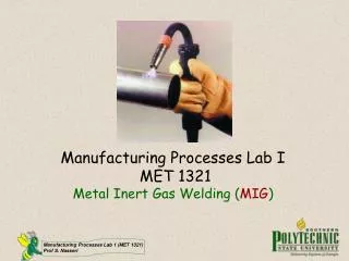
Metal Arc Gas Shielded (MAGS)MIG MIG is similar to MMA in that heat for welding is produced by forming an arc between a metal electrode and the workpiece.But we use very long electrode wire rolled on pulley. Applications Welding Sheets and Heavy plates, production welding by robots on cars
MIG is similar to MMA in that heat for welding is produced by forming an arc between a metal electrode and the workpiece; the electrode melts to form the weld bead. The main difference is that the metal electrode is a small diameter wire fed from a spool and a sheilding gas is used. As the wire is continuously fed, the process is often referred to as semi-automatic welding.
Advantages • Large gaps filled or bridged easily • Welding can be done in all positions • No slag removal required • High welding speeds • High weld quality • Less distortion of work piece
Equipmnt used in MAGS Three major elements are : Welding torch and accessories Welding control & Wire feed motor Power Source is Transformer Shielding Gas
Welding torch and accessories GAS DIFFUSER NOZZLE CONTACT TIP • The welding torch guides the wire and shielding gas to the weld zone. • Brings welding power to the wire also • Major components/parts of the torch are the contact tip, shielding gas nozzle, gas diffuser, and the wire conduit
Welding control and wire feed motor • Main function is to pull the wire from the spool and feed it to the arc • Controls wire feed speed and regulates the starting and stopping of wire feed
Sheilding Gas • Purpose of shielding gas is to protect the weld area from the contaminants in the atmosphere • Gas can be Inert, Reactive, or Mixtures of both • Argon, Helium, and Carbon Dioxide are the main three gases used in MAGS
Tungsten Arc Gas Shielded (TAGS)TIG TIG is similar to MMA in that heat for welding is produced by forming an arc between a metal electrode and the workpiece Applications Used in joining magnesium and Aluminium, stainless steels for high quality welding Thin sheet material
In the TIG process the arc is formed between a pointed tungsten electrode and the workpiece in an inert atmosphere of argon or helium. The small intense arc provided by the pointed electrode is ideal for high quality and precision welding. The electrode is not consumed during welding. Whenfillermetal is required, it must be added separately to theweldpool. There are two currents one for starting the arc the other switched on using a trigger or foot pedal, this is a high frequency current to maintain the arc, this is generated by a separte unit.
Advantages • Superior quality welding • Can be used in mechanised systems • Used to weld aluminium and stainless steels • Low distortion
Equipment used in TAGS Power source TIG must be operated with a constant current power source - either DC or AC Electrodes Electrodes for DC welding are normally pure tungsten. In AC welding, as the electrode will be operating at a much higher temperature, It should be noted that because of the large amount of heat generated at the electrode, it is difficult to maintain a pointed tip and the end of the electrode assumes a spherical or 'ball' profile.
Sheilding Gas Shielding gas is selected according to the material being welded. • Argon • Argon + Hydrogen • Argon/Helium • Helium is generally added to increase heat input (increase welding speed or weld penetration). Hydrogen will result in cleaner looking welds and also increase heat input, however, Hydrogen may promote porosity or hydrogen cracking.
Gas Welding (Oxy-acetylene) A number of welding processes use a flame produced by burning a mixture of fuel gas and oxygen. The gas usually used is Acetylene but other gases are also used. Separate cylinders and a hose pipe from each cylinder transports the gases to a torch. Gas and fuel mix in the torch burns @ 3100°C.
During the welding heat from the flame is concentrated on the joint edges until the metal melts and starts to flow. When the molten metal from both sides melts it starts to fuse, when the metal cools down the two parts become Permanently joined Additional Filler Metal is fed in by hand into the weld pool, at regular intervals where it becomes molten and joins with the parent metal.
The Oxy-acetylene welding Flame Carburising This kind of flame is used for welding High carbon steel & cast iron. Amount of acetylene gas is high in carburising. Neutral A flame resulting from the burning of gases supplied in the proper proportions for perfect combustion as approximately equal volumes of acetylene and oxygen Oxidising Widely used for cutting and not suitable for welding. When the amount of oxygen increases, the flame shortens but temperature goes too high.
Gases used Oxygenextracted from air and compressed into cylinders at high pressure. Cylinder is black.These cylinder have no welding joint these are complete tube like cylinders. Pressure contains 1800 psi Acetylene (C2H2) is a fuel gas. Cannot be compressed directly as explodes at high pressures. Cylinder colour coded maroon. We made these cylinders by welding three parts. Pressur contains 250 psi
Gas Pressure Regulators One gauge indicates the pressure of the cylinder and the other indicates the pressure in the supply pipe to the torch.
Welding torch Oxygen and acetylene are delivered to the torch by separate hoses. Each gas is controlled by a valve on the torch. The two gases mix in the torch and after they are ignited burn at the nozzle.
Flashback Arrestors These are positioned on both the fuel gas and oxygen supply between the hose and the regulator. Their purpose is to prevent the return of a flame through the hose into the regulator. Back Fire Back fire is a process in which a Tiny fire particle goes into the cylinder Through torch and pipe. As a result It cause big blast.
Filler Rods and fluxes Filler rods are used for welding the parts to each other. they come in different diameters. Fluxes protect the weld pool from contamination by oxygen and nitrogen, they are normally in paste form placed on a heated filler rod before welding begins.11
Advantages of gas welding Disadvantages of gas welding • The equipment is inexpensive, simple and is easily portable. • Useful for welding light metals such as automobile bodies and repair works. • Alarge variety of material can be welded. • Welds can be produced at reasonable cost. • Equipment must always be handled carefully as in certain circumstances acetylene is explosive. • A high temperature flame from a hand held torch is dangerous when handled carelessly. • It causes more distortion. • The process is not satisfactory for heavy sections.
Resistance welding Resistance welding uses the application of electric current and mechanical pressure to create a weld between two pieces of metal. Weld electrodes conduct the electric current to the two pieces of metal as they are forged together.The welding cycle must first develop sufficient heat to raise a small volume of metal to the molten state. This metal then cools while under pressure until it has adequate strength to hold the parts together.
Spot welding • Seam Welding
Spot welding Ideal for joining light sheet metal. The electrodes are made from copper. Pressure is applied to the electrodes and an electric current is passed through the circuit. The high resistance between the joint faces causes rapid heating and fusing of a small globule of metal from both faces.
Seam welding The rollers allow the workpiece to move through the welder continously. A stream of electrical pulses pass through the rollers and welds the joint
Resistance Welding Benefits • High speed welding • Easily automated • Suitable for high rate production • Economical • Resistance Welding Limitations • Initial equipment costs • Lower tensile and fatigue strengths • Lap joints add weight and material