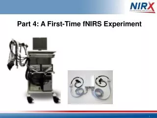
Part 4 : A First-Time fNIRS Experiment
100 likes | 493 Vues
Part 4 : A First-Time fNIRS Experiment. Simple Experiment The goal: setup a simple 4-source/4-detector montage on the motor cortex . Get good data!. Simple Experiment Open Folder: Experiments4x4_right_motor Read over NIRStar Manual!. Optode Montage/Array:. S 1. S 17. S 25.

Part 4 : A First-Time fNIRS Experiment
E N D
Presentation Transcript
Simple Experiment The goal: setup a simple 4-source/4-detector montage on the motor cortex. Get good data!
Simple Experiment Open Folder: Experiments\4x4_right_motor Read over NIRStar Manual!
S 1 S 17 S 25 S 33 S 41 S 9 NIRx uses this simple powerpoint-based montage editor for defining new optode arrays (montages). The numbering and colors of the circles correspond with Brain Products EEG caps. S 26 S 42 S 2 S 18 S 34 S 10 S 27 S 43 S 3 S 19 S 35 S 11 S 28 S 44 S 4 S 20 S 36 S 12 S 29 S 45 S 5 S 21 S 37 S 13 S 30 S 46 S 22 S 38 S 6 S 14 S 23 S 39 S 7 S 31 S 47 S 15 S 8 S 32 S 48 S 24 S 40 S 16 D 1 D 17 D 25 D 9 D 26 D 2 D 18 D 10 D 27 D 3 D 19 D 11 D 28 D 4 D 20 D 12 D 29 D 5 D 21 D 13 D 30 D 22 D 6 D 14 D 23 D 7 D 31 D 15 D 8 D 32 D 24 D 16 E 1 E 2 E 3 E 4 E 5 E 6 E 7 E 8 E 9 E 10 E 11 E 12 E 13 E 14 E 15 E 16 E 17 E 18 E 19 E 20 E 21 E 22 E 23 E 24 E 25 E 26 E 27 E 28 E 29 E 30 E 31 E 32
Sources 1-4 are pictured in Red, with numbering “S1”, …, “S4”. Detectors 1-4 are pictured in green, with numbering “D1”, …, “D4”. D 4 S 2 D 1 S 1 S 4 D 3 D 2 S 3 Channels of interest are indicated by a purple line drawn between sources and detectors.
Pictured right is a “topolayout”. It is a 2D abstraction of the montage/array setup of the probes. Each number in the pair refers to a Source (S) or Detector (D) channel pair, which represents a data channel of interest. The numbering corresponds to S-D (e.g., 4-3 = the channel between source 4 and detector 3). Topolayout
The Probe Setup Utility defines the 3D positions of the probes themselves, and the particular channels that will be analyzed later on during post-processing. Probe Setup