Download
1 / 10
100 likes | 307 Vues
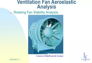
Ventilation Fan Aeroelastic Analysis . Rotating Fan Stability Analysis. (Courtesy of FläktWoods AB, Sweden). Ventilation Fan Modeling in LINFLOW. Rotating Fan Stability Analysis. Twin blade fan model : Rotating at 987 rpm Inner radius 0.68 m Outer radius 1.02 m.

E N D
Ventilation Fan Aeroelastic Analysis • Rotating Fan Stability Analysis. (Courtesy of FläktWoods AB, Sweden) LINFLOW 1.4
Ventilation Fan Modeling in LINFLOW • Rotating Fan Stability Analysis. Twin blade fan model: Rotating at 987 rpm Inner radius 0.68 m Outer radius 1.02 m LINFLOW 1.4
Steady Flow Analysis of Rotating Fan Steady Flow Absolute VelocityContours. LINFLOW 1.4
Structural Dynamic Analysis Rotating Fan Eigenmode table Structural model included fan blades + hub. Stability analysis was performed using the 8-10 first structural modes with the lowest natural frequencies. Structural model used LINFLOW 1.4
Ventilation Fan Aeroelastic Stability Analysis Aeroelastic Eigenfrequency Diagram Aeroelastic Damping Diagram One mode showed increasing damping requirements with increasing load, Which? LINFLOW 1.4
Ventilation Fan Stability Analysis Evaluation Unstable Mode Shape LINFLOW predicted an unstable 3.rd mode with a frequency of 382.6 Hz Measurements at full load later show that a maximum amplitude of vibration existed at 389 Hz LINFLOW 1.4
8 1 2 1 2 3 Ventilation Fan Experimental Response Evaluation Measurements at full load show that a maximum amplitude of vibration existed at 389 Hz Measured frequency response diagram. LINFLOW 1.4
Ventilation Fan Unstable Mode Animation (Click on Picture for Animation) LINFLOW 1.4
New Improved Ventilation Fan Geometry Aeroelastic improvements of the fan design Damping requirements for all aeroelastic modes now drop with increasing loading LINFLOW 1.4
New Ventilation Fan, Experimental Evaluation Measurements at full load on the aeroelasticly improved design show more then one order of magnitude lower stress levels on the fan surface. Measured frequency response diagram. (Return) LINFLOW 1.4