A simple bus
rd'/wr. Processor. Memory. enable. addr[0-11]. data[0-7]. bus. bus structure. A simple bus. Wires: Uni-directional or bi-directional One line may represent multiple wires Bus Set of wires with a single function Address bus, data bus Or, entire collection of wires

A simple bus
E N D
Presentation Transcript
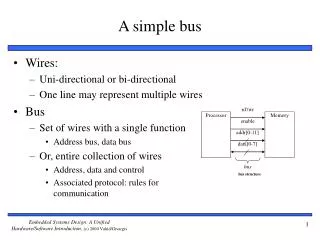
rd'/wr Processor Memory enable addr[0-11] data[0-7] bus bus structure A simple bus • Wires: • Uni-directional or bi-directional • One line may represent multiple wires • Bus • Set of wires with a single function • Address bus, data bus • Or, entire collection of wires • Address, data and control • Associated protocol: rules for communication
rd'/wr Processor Memory port enable addr[0-11] data[0-7] Ports • Conducting device on periphery • Connects bus to processor or memory • Often referred to as a pin • Actual pins on periphery of IC package that plug into socket on printed-circuit board • Sometimes metallic balls instead of pins • Today, metal “pads” connecting processors and memories within single IC • Single wire or set of wires with single function • E.g., 12-wire address port bus
Master Servant req wait data req 1 3 req 1 4 wait wait 2 3 data 2 4 data 5 taccess taccess 1. Master asserts req to receive data 1. Master asserts req to receive data 2. Servant puts data on buswithin time taccess 2. Servant can't put data within taccess, asserts wait ack (wait line is unused) 3. Servant puts data on bus and deasserts wait 3. Master receives data and deasserts req 4. Master receives data and deasserts req 4. Servant ready for next request 5. Servant ready for next request Fast-response case Slow-response case A strobe/handshake compromise
Microprocessor interfacing: interrupts • Suppose a peripheral intermittently receives data, which must be serviced by the processor • The processor can poll the peripheral regularly to see if data has arrived – wasteful • The peripheral can interrupt the processor when it has data • Requires an extra pin or pins: Int • If Int is 1, processor suspends current program, jumps to an Interrupt Service Routine, or ISR • Known as interrupt-driven I/O • Essentially, “polling” of the interrupt pin is built-into the hardware, so no extra time!
Microprocessor interfacing: interrupts • What is the address (interrupt address vector) of the ISR? • Fixed interrupt • Address built into microprocessor, cannot be changed • Either ISR stored at address or a jump to actual ISR stored if not enough bytes available • Vectored interrupt • Peripheral must provide the address • Common when microprocessor has multiple peripherals connected by a system bus • Compromise: interrupt address table
Micro-processor System bus 7 Inta 5 Priority arbiter Peripheral1 Peripheral2 Int 3 2 2 Ireq1 Iack1 6 Ireq2 Iack2 Arbitration using a priority arbiter • 1. Microprocessor is executing its program. • 2. Peripheral1 needs servicing so asserts Ireq1. Peripheral2 also needs servicing so asserts Ireq2. • 3. Priority arbiter sees at least one Ireq input asserted, so asserts Int. • 4. Microprocessor stops executing its program and stores its state. • 5. Microprocessor asserts Inta. • 6. Priority arbiter asserts Iack1 to acknowledge Peripheral1. • 7. Peripheral1 puts its interrupt address vector on the system bus • 8. Microprocessor jumps to the address of ISR read from data bus, ISR executes and returns • (and completes handshake with arbiter). • 9. Microprocessor resumes executing its program.
Serial protocols: CAN • CAN (Controller area network) • Protocol for real-time applications • Developed by Robert Bosch GmbH • Originally for communication among components of cars • Applications now using CAN include: • elevator controllers, copiers, telescopes, production-line control systems, and medical instruments • Data transfer rates up to 1 Mbit/s and 11-bit addressing • Common devices interfacing with CAN: • 8051-compatible 8592 processor and standalone CAN controllers • Actual physical design of CAN bus not specified in protocol • Requires devices to transmit/detect dominant and recessive signals to/from bus • e.g., ‘1’ = dominant, ‘0’ = recessive if single data wire used • Bus guarantees dominant signal prevails over recessive signal if asserted simultaneously
Arbitration • Carrier Sense - Multiple Access with Collision Avoidance (CSMA/CA) • Simultaneous requests for the bus result in one node transmitting (no thrashing) • CSMA/CD (e.g. Ethernet) exhibits thrashing • Bits on bus are either recessive (high) or dominant (low) • The first node to transmit a dominant bit during arbitration gets the bus
CAN vs. TTP • CAN - event triggered communication • Messages should communicate events not states • Suited for aperiodic communication • Priority determines which message goes first • TTP - time triggered communication • Messages should communicate states not events • Each node has a dedicated time slot for comm. • Node cannot be silenced by another node
TTP (Time-Triggered Protocol) TTP – more than just a protocol • Network protocol • Operating system scheduling philosophy • Fault tolerance approach Time-Triggered approach • Stable time base • Simple to implement the usual stuff • Cyclic schedules
TTP/C • TTP/C • A time-triggered communication protocol for safety-critical (fault-tolerant) distributed real-time control systems • Based on a TDMA(Time Division Multiple Access) media access strategy • Based on clock synchronization
FTU in TTP/C FTU Configuration Examples • Two active nodes, two shadow nodes • Three active nodes with one shadow nodes (Triple modular Redundancy) • Two active nodes without a shadow node
TTCAN • Communication can be ET or TT • Time slots are allocated • Reserved slot • Arbitration slot • Free slot • Requires global time synchronization
Wireless protocols: Bluetooth • Bluetooth • New, global standard for wireless connectivity • Based on low-cost, short-range radio link • Connection established when within 10 meters of each other • No line-of-sight required • e.g., Connect to printer in another room