Download
1 / 55
3.18k likes | 7.61k Vues
Chapter10 Fundamentals of Integrated Circuit Fabrication. Dr.Debashis De Associate Professor West Bengal University of Technology. Outline 10-1 Introduction 10-2 Fundamentals of Integrated Circuits 10-3 Types of Integrated Circuits

E N D
Chapter10 Fundamentals of Integrated Circuit Fabrication Dr.Debashis De Associate Professor West Bengal University of Technology
Outline 10-1 Introduction 10-2 Fundamentals of Integrated Circuits 10-3 Types of Integrated Circuits 10-4 Advantages and Disadvantages of Integrated Circuits 10-5 Scale of Integration 10-6 Crystal Growth and Wafer Preparation 10-7 Epitaxial Growth 10-8 Oxidation for Isolation 10-9 Photolithography for Pattern Transfer 10-10 Etching for Design 10-11 Diffusion for Doping 10-12 Ion Implantation for Doping 10-13 Metallization for Interconnection 10-14 Testing for Reliability 10-15 Packaging Protection 10-16 IC Symbols 10-17 Fabrication Steps for Different Circuits 10-18 Real-Life Applications
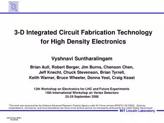
Objectives • This chapter deals with the fundamentals of integrated circuit fabrication. • In the field of nanotechnology, this basic idea of fabrication is very important from the point of view of semiconductor device engineering. • Semi- conductor device fabrication is the process used to create chips for devices that are a part of our everyday use. It is a multiple-step sequence of photographic and chemical processing during which electronic circuits are gradually created on a wafer substrate made of pure semi-conducting material. • The topics include : 1) electronic fundamentals, 2) crystal growth 3) wafer types, 4) transistor types, 5) basic design concepts, 6) mask making, 7) wafer processing, 8) materials used for fabricating the wafer, 9) equipments used for processing the wafer, 10) clean room standards, 11) testing and reliability control, 12) assembly 13) packaging, and different IC types.
INTRODUCTION: • In the world of semiconductor devices and integrated circuits, silicon is the commonly used semiconductor material, and it is mostly used as a substrate material. • For example, solar cells made of silicon wafers are cheaper and can be used for practical applications by common people. • Of late, it has been observed that GaAs fabrication has advanced compared to silicon due to its greater thermal stability, direct band gap and higher electron mobility. However, GaAs fabrication is a difficult process and the cost is also very high. • Today compound semiconductors are the main point of attraction. IV–IV, III–V and II–VI are the common compound semiconductors used in research and industry. • Among these the compound semiconductor III–V is widely used as it has multiple applications in LED, LASER, etc. gallium arsenide (GaAs), indium phosphide (InP), gallium phosphide (GaP) and gallium nitride (GaN) and aluminum nitride (AlN)—are the III–V compound which are widely used. Optoelectronic devices using III–V compound.
FUNDAMENTALS OF INTEGRATED CIRCUITS: The fabrication of integrated circuits is an art. From the age of LSI (large-scale integration) to VLSI (very-large-scale integration), the device dimension has reduced by a large amount, but at the same time 100% of its switching speed has increased. ULSI (ultra-large-scale integration) is used for low-dimensional nanostructure devices. Nowadays, the use of MBE(molecular beam epitaxy), MOCVD (metal-organic chemical vapour deposition) and CBD (chemical bath deposition), make it possible to fabricate the nanostructure semiconductor devices in the form of Quantum Well, Quantum Wire and Quantum Dot. Nano devices are typically 1–100 nm (in each direction) in dimension. The smaller the devices, greater is the challenge of fabrication. As shown in Fig. 10-1, there has been a shift from the bipolar technology to the MOS technology. A projection up to the year 2010 shows that an approximate 95 percent of the market will be composed of MOS devices, and the remaining 5 percent will be bipolar. The bold arrowhead line shows the average trend line in the figure.
FUNDAMENTALS OF INTEGRATED CIRCUITS: With devices getting smaller and smaller, the number of their components/chips has been increasingly getting bigger and bigger with time. A plot in Fig. 10-2 projected up to year 2010 shows the number of components/chip vs. time (year). The bold arrowhead line shows the average trend line in the figure. Figure 10-3 shows the drop in feature size projected up to the year 2010. The bold arrowhead line shows the average trend line in the figure.
TYPES OF INTEGRATED CIRCUITS: 1. Monolithic IC: In the Monolithic IC the entire circuit is built into a single piece of semiconductor chip, which consists of active and passive components. The most commonly used integrated circuits, microprocessors, memories, etc., are all monolithic. 2. Hybrid IC: In Hybrid IC the electronic circuit is generally integrated in the ceramic substrate using various components and then enclosed in the single package. The hybrid IC consists of several monolithic ICs con-nected by metallic interconnects mounted on a common substrate. Hybrid IC technology bonds various substrates either at the die level or at the wafer level. This technology streamlines the connections between different semiconductor chips by replacing wire bonding. This process achieves an accelerated, streamlined and less costly process. Hybrid IC allows increase in communication bandwidth and facilitates higher system yield.
ADVANTAGES AND DISADVANTAGES OF INTEGRATED CIRCUITS: • The advantages of integrated circuits are as follows: • 1. Small in size due to the reduced device dimension • 2. Low weight due to very small size • 3. Low power requirement due to lower dimension and lower threshold • power requirement • 4. Low cost due to large-scale production • 5. High reliability due to the absence of a solder joint • 6. Facilitates integration of large number of devices • 7. Improves the device performance even at high-frequency region • The disadvantages of integrated circuits are as follows: • 1. IC resistors have a limited range • 2. Generally inductors (L) cannot be formed using IC • 3. Transformers cannot be formed using IC
SCALE OF INTEGRATION: • Historically, the first semiconductor IC chips held one diode/transistor. Advancement of technology enabled us to add more and more transistors. • The first to arrive was small-scale integration (SSI), then improvements in technique led to devices with hundreds of logic gates—large-scale integration (LSI) • Present day micro- processors have millions of logic gates and transistors. Intel co-founder, Gordon E. Moore, in 1965 published a paper on the future projection of IC technology. • Moore’s Law is responsible for “smaller, cheaper and more efficient IC”. Gordon Moore’s empirical relationship is cited in a number of forms, but its essential thesis is that the number of transistors that can be manufactured on a single die will double every 18 months.
Types of IC Chips: Analog: Analog chips are small transistor count precision circuits. Amplifiers, filters, sensors, etc. fall into this category. ASIC or application specific integrated circuits: ASIC brings a lot more of functionality into the same area. These are IC’s that are created for specific purposes—each device is created to do a particular job. The common application area for this is Digital Signal Processing—signal filters, image compression, etc. SOC chips are highly complex mixed signal circuits (digital and analog all on the same chip). A network processor chip or a wireless radio chip is an example of a SoC. The planar technology for IC fabrication consists of the following processes: 1. Crystal growth of the wafer 2. Epitaxial growth 3. Oxidation 4. Photolithography 5. Etching 6. Diffusion 7. Ion implantation 8. Metallization 9. Testing and packaging
CRYSTAL GROWTH AND WAFER PREPARATION: • Crystal growth and wafer preparation is the most fundamental step in device fabrication. Various crystal growth techniques are used to form the bulk crystal. • One of the methods is the Czochralski process. • A small seed crystal of silicon is attached to the top of a rod and lowered into a crucible of molten silicon to which acceptor impurities have been added. As the rod is very slowly pulled out of the ‘melt’ under carefully controlled conditions, we find that a single p-type or n-type crystal ingot of the order of several inches has grown. • The ingot is subsequently sliced into round wafers to form the substrate on which all integrated components are fabricated. One side of each wafer is lapped and polished to eliminate surface imperfections before proceeding with the next process.
Czochralski process: Czochralski process
EPITAXIAL GROWTH: • Epitaxy, derived from Greek epi ‘upon’ and taxis ‘arrangement’, refers to the growth of crystals on a crystalline substrate that determines their orientation. • Epitaxy involves the extension of the substrate lattice by the overgrowth of a layer of identical material. This is known as homoepitaxy or autoepitaxy. For example,Si on Si or Ga As on Ga As. • If the epitaxial layer and the substrate are chemically and often crystallo graphically different, then this is called heteroepitaxy. For example, Si (diamond lattice) on sapphire (hexagonal) or Ga As on Si. • The epitaxial process is used to form a layer of single-crystal silicon on an existing crystal wafer of the same or different material. • Epitaxial growth is performed in a special furnace called the reactor. Silicon wafers are inserted in the reactor and heated to a temperature of900–10000C. The temperature varies from substrate to substrate.
Epitaxial growth technology uses the hydrogen reduction of gases like silane (SiH4) or silicon tetrachloride (SiCl4) as the source for the silicon to be grown. Silane has two advantages. It requires a lower temperature and has a faster growth rate than silicon tetrachloride. The chemical reaction for the hydrogen reduction of SiCl4 is: 1200 0C SiCl4 + 2H2 Si + 4HCl And that for SiH4 is: H2 atmosphere, 10000C SiH4 Si +2H2 For example, an n-type epitaxial layer, typically from few nanometre to few micrometre thick, is grown into a p-type substrate having resistivity of approximately few cm. Since epitaxial growth requires the production of epitaxial films of impurity concentrations, it is essential to introduce impurities, such as Phosphine (PH3) for n-type doping or Diborane (B2H6) for p-type doping into the EPITAXIAL GROWTH:
OXIDATION FOR ISOLATION: Silicon technology has the natural ability to grow an oxide layer on the SiO2 layer.As a passivating layer SiO2 has the following characteristics: 1. The impurities that are used to dope the silicon do not penetrate n-type Si wafer.Thus, when used with the masking techniques,selective doping of specific regions of the chip is accomplished. 2. It is capable of being etched by hydrogen fluoride (HF). Thermal oxidation of silicon is achieved in the presence of water vapour; this process is called wet oxidation. The chemical reaction for this process is: Si + 2H2O → SiO2 + 2H2 Dry oxidation of oxygen: Si + O2 → SiO2 The thickness of the oxide layers is generally in the order of 0.02 mm to 2 mm.Process temperature, impurity concentration, and processing time are several of the factors that influence the thickness of the SiO2 layer.
PHOTOLITHOGRAPHY FOR PATTERN TRANSFER: • Photolithography is the optical process of transferring geometric shapes on a mask to the surface of a silicon wafer. • The steps for the photolithographic process are: photo resist coating, soft-baking, mask alignment, UV exposure and development, and hard-baking. • In the starting of the photolithographic process, the wafer is coated with a uniform film of a photosensitive emulsion. • The photo resist is slightly hardened by soft-baking and then selectively removed by projection of UV light through mask. • The monolithic fabrication technique requires the selective removal of the insulator layer of SiO2 to form openings through which impurities can be diffused.
Photolithography processes using negative and positive photoresist:
Mask Alignment and UV Exposure: The most important step in the Photolithography process is mask alignment. In general, photo-mask is a plastic or glass plate with a pattern of emulsion. The mask is aligned on the top surface of the wafer, so that the pattern can be transferred on it. Once the mask has been accurately aligned with the pattern on the wafer’s surface, the photo resist is exposed through the pattern on the mask with a high intensity ultraviolet light. • There are three primary exposure methods: • Contact Printing • Proximity Printing • Projection Printing
Contact printing: In this technique the resist-coated silicon wafer is brought into physical contact with the photo-mask, as shown in Fig. 10-8(c). The wafer is held on a vacuum system. The system is exposed with UV light from the top of the mask as the wafer is in contact position with the mask. As the photo resist and the mask are in direct contact, a high resolution is possible in contact printing. But the disadvantage with contact printing is that the dust trapped between the resist and the mask can damage the mask and cause defects in the pattern.
Proximity printing: This technique is almost similar to contact printing technique except that a small (10–15 mm) gap is maintained between the mask and the wafer [see Fig 10-8(d)]. It is very important to note that the gap minimizes, but may not eliminate the damage to the mask.
Projection printing: Projection printing is the most advanced technique, it avoids mask damage. An image of the patterns on the mask is projected onto the resist-coat which is a certain height away as shown in Fig. 10-9. To achieve high resolution only a small portion of the mask is imaged. This small region image field is scanned over the surface of the wafer. Projection printers that step the mask image over the wafer surface are called step-and-repeat systems having several nano-metre resolution. Figure 10-10 (a) shows response curves for negative and positive resist after the exposure and development.
ETCHING FOR DESIGN: Etching selectively removes layers of SiO2, metals, and poly-silicon, according to the desired patterns delineated by the resist. The two major methods of etching are wet chemical etching or dry etching. The windows are created by the photolithographic process and subsequent etching process in the desired pattern implemented by the masking process .
Different Types of Etching: 1. Wet Chemical Etching: Wet etching is accomplished by partial submersion of the wafer in an acid bath having some definite concentration. Etching solutions are housed in a temperature-controlled baths.
Different Types of Etching: 2. Dry Chemical Etching: Dry processing effectively etches desired layers through the use of gases, using either, a chemically reactive gas, or through physical bombardment of argon atoms. Dry etching is commonly used due to its ability to better control the etching process and decrease contamination levels. 3. Chemical Plasma Etching: Plasma etching systems have been developed that can effectively etch silicon, silicon dioxide, silicon nitride, aluminium, gold, glass, etc. The barrel or cylindrical, and the parallel plate or planar are the two kinds of plasma etching reactor systems are generally used. The typical reactor consists of a vacuum reactor chamber
Different Types of Etching: 4. Chemical Plasma Etching:
Different Types of Etching: 5. Ion Beam Etching: Ion beam etching is similar physical etching processes which use a beam of low-energy ions to remove material. By an electrical discharge the ion beam is extracted from an ionized gas such as argon or argon/oxygen or plasma. An electrical discharge creates an ion plasma with the energy of a few hundred electron volts. 6. Reactive Ion Etching: Reactive ion etching (RIE) is a combination of chemical and physical etching. During RIE, a wafer is placed in a chamber with an atmosphere of chemically reactive gas either CF4 or CCl4 at a low pressure. The ions strike the wafer surface vertically.
DIFFUSION FOR DOPING: • Diffusion is a process of introduction of impurities into the substrate layer in the planar process. • The introduction of controlled impurity concentrations is performed in a diffusion furnace at a temperature of about 1000C over several hours for silicon substrate.
ION IMPLANTATION FOR DOPING: • In Ion implantation the ionized particles are accelerated through an electrical field and targeted at the semiconductor wafer.
TESTING FOR RELIABILITY: • After all the fabrication processes are done successfully, the semiconductor device is tested thoroughly • through the different characterization processes. IC’s are fabricated by the batch process ,so some of the IC may not perform according to standard. • An electronic tester presses tiny probes against the chip to check its functional property. • For example, checking of truth table for digital logic gates.ICs are often designed with “self testability features” for example, built-in self-test (BIST) for speed testing. • These processes reduce test.costs and time. The standard checking can be done by the reliability testing process by an IC tester.
PACKAGING PROTECTION: • The last step of this process is packaging. • Packaging is done according to the dimension of the product type, and the requirements of the manufacturer. The wafer is certified then the wafer is broken into small individual dies. • Small wires are bonded to connect pads to the external connection pins. The most common packaging is dual input packaging or DIP, mostly used in digital IC. • Pin grid array (PGA) and leadless chip carrier (LCC) packages are used in modern VLSI design. After testing and packaging, the product is sent to the market for sale.
FABRICATION STEPS FOR DIFFERENT CIRCUITS: 1. Fabrication of Resistors in Integrated Circuits: Resistors in IC can be made by the base diffusion method. The resistor is made up of a p-layer within one n-type island or the reverse, as shown in Fig. 10-17. Resistance R =row *LlA where, r is the resistivity, l =length and A =area. Resistance value depends on l, A and r.
Difference between OHOMIC contact and SCHOTTKY contact: Schottky diode or contact is a metal-semiconductor diode or contact having characteristics similar to a p–n junction. When the metal is deposited directly on the Semiconductor surface, the SCHOTTKY CONTACT is produced. The junction of the metal semiconductor, the same metal-doped layer, produces a linear behavior, i.e., Ohomic behavior. The junction that follows OHM’s LAW, i.e., linear nature in I–V characteristics forms an OHOMIC CONTACT (see Fig. 10-19).
Electron availability is very high in the metal as the Schottky diode is made with the directly deposited metal on semiconductor surface. • Electron availability is very high in the metal as the Schottky diode is made with the directly deposited metal on semiconductor surface. The applications of SCHOTTKY contact: Electron availability is very high in the metal as the Schottky diode is made with the directly deposited metal on semiconductor surface. Schottky diode is a majority carrier device. As the time of injection of the electrons from conduction band to metal decreases, the switching becomes faster. This diode has low reverse and forward impedances. So, it is used in high-speed switching devices.
Steps of Fabrication of Capacitors: • In ICs, capacitors are fabricated using the depletion region capacitance of a Reverse bias p–n junction, or by MOS structure. • In case of junction capacitance, the magnitude depends on the dimension and type of the junction, and the applied bias. A depletion capacitance can be formed using MOS structure. A parallel plate capacitor is obtained by MOS technique. • A pair of n layers is deposited to form source (S) and drain (D),as shown in Fig. 10-20. A thin silicon dioxide (SiO2) layer acts as the dielectric layer. • The heavily doped n-region and the Al layers act as the two plates of the capacitor. The magnitude of the capacitance is generally very small, in the order of pico-farad.
Steps of Fabrication of the Transistor Circuit: • A step-by-step process will now be followed for the fabrication of a transistor circuit, as shown in Figs.10-21(a) and 10-21(b). Step I: On the p-type substrate a layer of n-type semiconductor is formed.
Steps of Fabrication of the Transistor Circuit: Step II: Photolithographic process using UV ray source.
Steps of Fabrication of the Transistor Circuit: Step III: The p diffusion at the window region is done by ion implantation technique or by chemical deposition.
Steps of Fabrication of the Transistor Circuit: Step IV: Again, to form a p-region within an n-region, another set of masks are used, and the second step of photolithography is performed.
Steps of Fabrication of the Transistor Circuit: Step V: The third-level mask is used to get the pattern, as shown in Fig. 10-21(f). Multiple types of masks and subsequent photolithography is done to achieve the desired complicated circuit.
Steps of Fabrication of the Transistor Circuit: Step VI: Before metallization, the metal mask of the desired pattern is used. In the mask, the blank space is kept where we want to go for metallization [see Fig. 10-21(g)].
Steps of Fabrication of the Transistor Circuit: Step VII: Metal interconnections for different contact points are used, as shown in Fig. 10-21(h). Metallization is performed at a very low pressure, at about 106 torr. Total metallization is preformed in a closed chamber and the room should be clean. High pure gold or Al is used for metallization. Purity is 99.9999%.
The Schottky Diode: In Fig. 10-22, terminal 1 forms the ohmic contact, because Al is deposited on the n region and not on the n– region, but terminal 2 forms the Schottky contact.The Schottky contact together with the two terminals forms the Schottky diode.