Download
1 / 24
240 likes | 337 Vues
Dive into Shekhar Mishra's program at Fermilab focusing on ILC and SRF R&D with a detailed mission, goals, and significant accomplishments in the field. Explore infrastructure development, advancements in cavity and cryomodule design, collaborations, and plans for future projects. Details on alignment with Project X/ILC, industrialization, cavity R&D progress, improvements in fabrication and processing techniques, and the involvement of US and international vendors are highlighted. Track the developments in cryogenic systems and units testing facilities, including key milestones achieved at Fermilab's test areas. Follow the progress towards meeting Phase-1 goals and expansion plans for the program. Discover the critical role of Fermilab in advancing the ILC and SRF technology landscape.

E N D
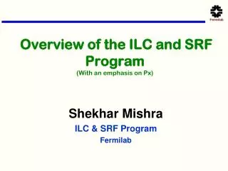
Overview of the ILC and SRF Program(With an emphasis on Px) Shekhar Mishra ILC & SRF Program Fermilab
ILC R&D and SRF Infrastructure ILC R&D Mission: Work with the GDE Americas Regional Team (ART) to develop the ILC machine design Goal Participate in the Technical Design Phase (TDP) Work towards GDE SRF goals S0: Cavity gradient of 35 MV/m; good yield S1: Cryomodules with average gradient > 31.5 MV/m S2: One or more ILC RF unit with ILC beam parameters Design improvements for cost reduction Fermilab as a possible site and trusted international partner SRF Infrastructure Mission: Develop infrastructure and expertise in SRF technology at Fermilab Goals: Prepare FNAL Infrastructure with a capacity of 1 CM/month for Project X or a future ILC Project Perform R&D to improve SRF performance, reduce cost Build needed FNAL SRF Infrastructure Operate SRF facilities & train staff in SRF technology Transfer SRF technology to U.S. industry Collaborate with U.S. & International ILC/Px partners
FY08 Accomplishments Cavities ILC cavities built by U.S. vendors (AES, Roark/Niowave) Collaborated with Cornell, Jlab and ANL to process & test ILC 9-cell cavities in the U.S. Performance is comparable to DESY First U.S. assembled 1.3 GHz cryomodule complete (DESY kit) Processing cavities, ordered parts towards CM2 (To be fabricated in FY09) Type-IV Cryomodule Design in collaboration with ILC DESY 3.9 GHz cryomodule nearing completion (March 09) Excellent cavity performance Infrastructure Commissioned Vertical Test System (VTS1) at IB1 Commissioned Horizontal Test System (HTS) at MDB Cryomodule assembly facility completed ( ICB, MP9) Commissioning new ANL/FNAL joint cavity processing facility RF unit test facility at New Muon Lab under construction
Project X/ILC Alignment 38 ILC-like cryomodules are required for Project X. In detail they will not be identical to ILC: Gradient: 25 MV/m Beam current: 20 mA 1.25 msec 5 Hz Focusing: Quadrupole element required in each CM Consistent with upgrade path 1.25 2.5 msec pulse length 5 10 Hz pulse rate Development Plan Development strategy based on ILC “plug compatibility” Cryomodule development is through the ILC program Cavity Fabrication, Processing and Test Infrastructure; Cryomodule Assembly Facility and ILCTA-NML Test Area are constructed via the SRF program: 1 CM/month assembly capability and beam testing of a complete rf unit
Project-X/ILC Alignment Industrialization Production of 38 ILC-like (plus 8 b=0.8) CMs over a 2-3 year period is consistent with Fermilab Cryomodule Assembly Facility (CAF) capabilities in ~2013; however, the production rate remains well below that required by ILC • This activity could represent the initial phase of an industrialization buildup for ILC and get US industry involved. • Operations • Project X will provide invaluable operational experience in the operations of a linac of roughly 1% of ILC
US: Cavity R&D Cavities are fabricated using US and German Vendor Developing US and Canadian vendor (AES, Roark, Niowave, PAVAC) Improving fabrication techniques aided with material and 1-cell R&D Developing and Improving processing techniques to Increase yield Higher Gradient with large Q and small Field Emission ILC Goal PX Goal Px Yield with qualified vendor ~ 70% Px Yield with U.S. vendor ~50%
Thermometry locates Defect AES 1 Optical Image
R&D to Improve Gradient and Yield Pits appear after EP !
Laser Melting of Nb Surface Preliminary experiments show a pit cannot be removed by BCP or EP, even after ~150 um removal Fermilab is investigating: Laser Melting 100 µm 14 µm
Next at FNAL: Cryomodule 2 Seven (eight) good cavities for CM 2 Average Vertical Test gradient is ~36 MV/m Remaining cavity and spare will be selected based on upcoming test results Design of He Vessel Finished 1st Dressing with AES cavity March 09 Tuner and Cold Mass from INFN Power Coupler from SLAC Cryomodule 2 assembled in 2009 * based on last process/test result at Jefferson Lab Cryomodule 1 Assembled at Fermilab using DESY Kit
Cryomodule(s) Test with Beam Capture Cavity 1 (CC1) CC2 Cryomodules RF Gun Gun RF System CC2 RF System 5MW RF System for Cryomodules Space for 10 MW RF System Fermilab is building a CM test area with Beam at NML. 12
RF Unit Test Facility at New Muon Lab (NML) • Cryogenic System Operational (Aug. 2007) • Delivery of First Cryomodule to NML (Aug. 2008) • Cryomodule Ready for Cool down (Spring 2009) • Cold RF Testing of Cryomodule (Summer 2009) • Delivery of 2nd Cryomodule to NML (Fall 2009) • Installation of Gun and Injector (2010) • First Beam (2011) • Full RF Unit Testing (3 Cryomodules) (2012)
Progress at NML Test Facility Cryogenic Vacuum Pump CM Feed Can 1st Cryomodule Installed 5 MW RF system He Refrigerator Control Room
NML FY09 Plans Complete Phase-1 Goals Move CC2 to NML Commission RF systems for CM1 & CC2 Commission Cryogenic System using CC2 Cooldown CM1 Install RF Power Distribution for CM1 Complete Infrastructure to Cooldown, RF Power, and operate CC2 & CM1 Vacuum, RF, Cryo, Interlocks, LLRF, Controls, etc. Begin Operation of CC2 Begin Cold RF Testing of CM1 Begin Work Towards Phase-2 (Budget Permitting) Begin Procurement of Injector (gun, magnets, etc.) and Test Beamline (dumps, magnets, etc.) Begin Building Extension Construction
3.9 GHz Status • 8 Cavities fabricated (including 2 prototypes) • More than 60 vertical tests conducted at A0 • Cavities must exceed 19 MV/m, low field emission, good Q to ‘pass’ • 5 good cavities • 5 Cavities welded into helium vessels • 4 ‘dressed’ cavities successfully completed Horizontal Testing at ILCTA_MDB/HTS • All cavities have achieved >22 MV/m at 2K • Low field emission • Q within specs • String Assembly complete early January • Cold Mass Assembly in progress • Expect to ship complete module in March 2009. • Complete module will be installed at DESY Cryomodule Test Bed and cold power tested prior to installation in FLASH in early 2010 Bare 3.9 GHz Cavity Q vs E - Vertical Tests Dressed Cavity into HTS Q vs E - all Horizontal Tests Completed String Assembly Cold Mass Assembly
Infrastructure Need for Px and ILC Technology Transfer to Industry The Goal of Project-X construction is to achieve 1 CM/month assembly for the 1.3 GHz Cryomodule Cavities ~125 per year (assuming 80% yield) Processing Bulk (150 micron etch) ~125 per year (US Industry) Fine (20 micron etch) ~190 per year (Assuming on average 1.5 cycle/cavity) (US Laboratory) Vertical Testing ~180 per year Horizontal Testing ~ 60 per year (Assume ½ for QC) Cryomodule Assembly 1 per month Cryomodule Testing 1 per month About 50% additional capacity is needed for the 325 MHz cavities. We have DOE reviewed detail plan for this SRF Infrastructure development Major change is our thoughts on Processing Facility
FNAL-ANL Cavity Processing Facility New High-pressure rinse system • In FY08 most of the US cavity processing was done using Jlab and Cornell • ANL and Fermilab has jointly built a processing facility at ANL. • It provides a complete processing of 1.3 GHz cavities: • electro-polishing, ultrasonic cleaning, high-pressure rinse, assembly, etc. • Facility nearing completion (HPR, ultrasonic, fixtures) • Three single-cell cavities and one 9-cell cavity electro-polished so far • Optimization of processing procedure is in progress • 9 cell Cavity will be processed in Spring 09 • Electro-polishing Room New Ultrasonic cleaning system
Vertical Cavity Test Facility 26 cavity tests in FY08/FY09, where “test” = cryogenic thermal cycle Performance tests for 9-cell & single-cell elliptical cavities, and a SSR1 HINS cavity Cavity tests dedicated to instrumentation development, e.g., variable coupler, thermometry, cavity vacuum pump system Cavity tests dedicated to facility commissioning, e.g., for ANL/FNAL CPF
Cavities to accommodate ILC/SRF R&D 9-cell and 1-cell elliptical ILC cavities HINS/Project X SSR1 SSR2 TSR 9-cell elliptical cavities VTS requirements VTS1 is sufficient to support FY09, FY10 test plans VTS2 with larger diameter operational by end of CY2011 to support SSR2, TSR, and increased throughput VTS3 needed somewhat later Planned upgrades for ultimate capacity ~250 cavity tests/yr 2 cavities per cryogenic cycle, singly RF tested Cryogenic system & infrastructure upgrades Two more VTS cryostats – collaborate with Indian Institutions VCTF upgrade plans VTS 2&3 pits & staging area Do not fit in VTS1
Horizontal Test Stand • Commissioned in 2007 with 1.3 GHz dressed cavity • Operational in 2008, tested four 3.9 GHz cavities • First cavity: 8 months between cavity’s arrival and departure (Commissioning) • Fourth cavity: 2 weeks between cavity’s arrival and departure (turnaround time goal achieved)
Plan: SRF Infrastructure Development Vertical Test Stand Add 2 more cryostat with larger radius to accommodate Spoke Resonators. Horizontal Test Stand Build a new Horizontal Test Stand with 2 cavity length Cryomodule Test Stand New design based on DESY experience Processing Facility US Industry involved in Bulk Processing Double the Jlab and ANL/FNAL present capacity and add redundancy New facility for post processing treatment, tuning etc. NML Upgrade Cryogenic Beam Test and Diagonastic 2 ILC RF Units (6 CM and 2 RF Systems)
ILC Collaborations Px Collaboration US Collaboration ANL: EP development and cavity processing Cornell: Cavity processing & test, materials R&D MSU: HPR, Cavity vendor development and cost TJNL: EP cavity processing and test SLAC: RF power, klystrons, couplers NW,UW/NHML, U of Chgo: Materials R&D IIT, NIU: joint appointments International Collaboration DESY: 3.9 GHz, cryomodule kit, TTF, materials KEK: Cavity R&D, ATF II INFN: tuners, HTS, NML gun cathodes TRIUMF: cavity development, tuners CERN, DESY, KEK, INFN, etc: Type IV CM design India: CM Design, infrastructure, cavities, etc China: Cavity and SRF development ( IHEP, PKU)
Summary US ILC and SRF Infrastructure programs have been making progress Cavity (eight with excellent gradient) CM2 assembly to start CM1 to be cold with RF VTS, HTS, ANL/FNAL Processing commissoned These R&D are in line with the needs of a significant part of Project-X. This would get the US industry involved Infrastructure construction at Fermilab is aligned with the Project-X construction needs and initial US industrial efforts that would be needed for ILC regardless where it is located.