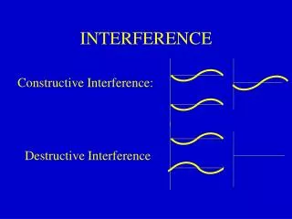
INTERFERENCE
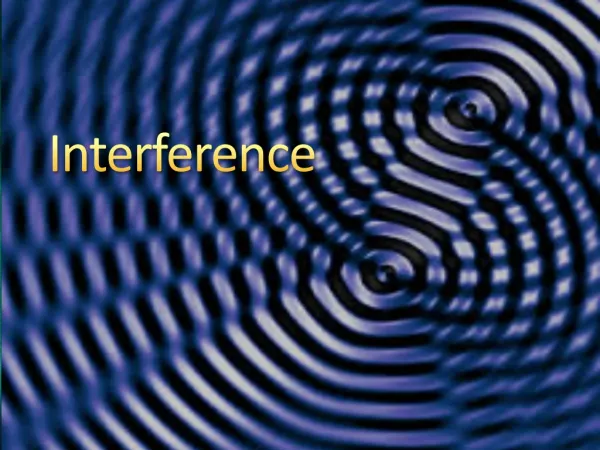
INTERFERENCE. DIVISION OF WAVEFRONT. Division of wavefront When light from a single point source is incident on two small slits, two coherent beams of light can be produced . Each slit acts as a secondary source due to diffraction.

INTERFERENCE
E N D
Presentation Transcript
INTERFERENCE DIVISION OF WAVEFRONT
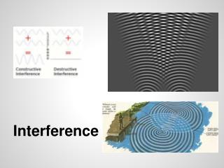
Division of wavefront When light from a single point source is incident on two small slits, two coherent beams of light can be produced. Each slit acts as a secondary source due to diffraction. If an extended source is used, each part of the wavefront will be incident on the slit at a different angle. Each part of the source will then produce a fringe pattern, but slightly displaced. When the intensity of all the patterns is summed the overall interference pattern may be lost. However a line source parallel to the slits is an exception.
Young's Slits Experiment The diagram below shows light from a single source of monochromatic light incident on a double slit. The light diffracts at each slit and the overlapping diffraction patterns produce interference.
The first bright fringe is observed at P. Angle PMO is θ N is a point on BP such that NP = AP Since P is the first bright fringe BN = λ For smallvalues of θ, AN cuts MP at almost 900 giving angle MAQ = θ and hence angle ΒΑΝ = θ Again providing θ is very small, sin θ = tan θ = θ in radians
From triangle BAN: θ = λ / d and from triangle PMO: θ = Δx / D So λ / d = Δx / D Therefore
Two points to note: • This formula only applies if x<<D, which gives θ small. This is likely to be true for light waves but not for microwaves. • The position of the fringes is dependent on the wavelength. If white light is used we can expect overlapping colours either side of a central white maximum. The red, with the longer wavelength, will be the furthest from this white maximum (Δxred > Δxviolet since λred > λviolet).
Example A laser beam is incident on two narrow slits of separation (0.250±0.002)mm. An interference pattern is produced on a screen (2.455±0.005)m from the slits. The spacing across ten fringes is measured as (62.0±0.5)mm. (a) Calculate the wavelength of the light. Δx = 62.0x10⁻³/10 and Δx= λD/d 62.0x10⁻³/10 = λx2.455/0.250x10-3 λ=631nm (b) State the uncertainty in the wavelength and express the wavelength as (value±absolute uncertainty). Using % uncertainties: Uncertainty in d =(0.002/0.250)x100=0.8% Uncertainty in D=(0.005/ 2.455)x100=0.2% Uncertainty in Δx=(0.5/62.0)x100=0.8%
The uncertainty in D can be ignored since it is less then one third of the others. Total % uncertainty is = =1.1% 1.1% of 631nm = 7nm so wavelength = (631 ± 7)nm • State one way in which you might be able to improve the accuracy of the experiment, give a reason. • Measure across more fringes, for example twenty fringes. This would reduce the percentage uncertainty in Δx. • (d)State, with a reason, if the fringe spacing increases, decreases or remains the same if red laser light is replaced by a Helium-Cadmium laser with a wavelength of 422nm. • Since the wavelength has decreased the fringe spacing decreases, since Δx a λ