Download
1 / 57
610 likes | 832 Vues
Least-squares Migration and Full Waveform Inversion with Multisource Frequency Selection. Yunsong Huang. Sept . 5, 2013. Introduction Multisource Frequency Selection Least-squares migration (LSM) test on 2D and 3D synthetic data Full Waveform Inversion (FWI)

E N D
Least-squares Migration and Full Waveform Inversion with Multisource Frequency Selection YunsongHuang Sept. 5, 2013
Introduction Multisource Frequency Selection Least-squares migration (LSM) test on 2D and 3D synthetic data Full Waveform Inversion (FWI) test on 2D synthetic and field GOM data Resolutions for Wave Equation Imaging Summary Outline
Gulf of Mexico Seismic Survey 4 d Predicted data Observed data 1 Time (s) Goal: Solve overdetermined System of equations for m Lm = d 1 1 0 Lm = d 6 X (km) 2 2 Lm = d . . N N . m
Details of Lm = d 4 d 1 Time (s) 0 6 X (km) Reflectivity or velocity model G(s|x)G(x|g)m(x)dx = d(g|s) Predicted data = Born approximation Solve wave eqn. to get G’s m
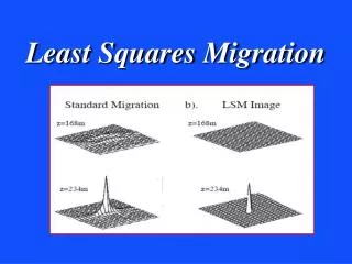
Standard Migration vs Multisource Migration Romero, Ghiglia, Ober, & Morton, Geophysics, (2000) Given: d1 and d2 Given: d1+ d2 Find: m Find: m Soln: m = (L1 + L2)(d1+d2) T T T Soln: m=L1 d1 + L2 d2 T T = L1 d1 + L2 d2 Benefit: Reduced computation and memory Liability: Crosstalk noise … T T + L1 d2 + L2 d1 Src. imaging cond. xtalk
Multisource LSM & FWI Inverse problem: 1 ~ ~ m || d – L m ||2 arg min J = 2 Dd misfit Iterative update: ~T m(k+1) = m(k) + aLDd K=1 T T L1Dd1 + L2Dd2 K=10 T T + L1 Dd2 + L2 Dd1
Brief Early History: Multisource Phase Encoded Imaging Migration Romero, Ghiglia, Ober, & Morton, Geophysics, (2000) Waveform Inversion and Least Squares Migration Krebs, Anderson, Hinkley, Neelamani, Lee, Baumstein, Lacasse, SEG Zhan+GTS, (2009) Virieux and Operto, EAGE, (2009) Dai, and GTS, SEG, (2009) Biondi, SEG, (2009)
Goal of the Study Multisource optimization for marine LSM/FWI Standard optimization for LSM/FWI Speed and quality comparison
Introduction Multisource Frequency Selection Least-squares migration (LSM) test on 2D and 3D synthetic data Full Waveform Inversion (FWI) test on 2D synthetic and field GOM data Resolutions for Wave Equation Imaging Summary Outline
Land Multisource FWI Fixed spread Simulation geometry must be consistent with the acquisition geometry
Marine Multisource FWI Mismatch solution with marine data Observed marine data purify Freq. encoding Decode & mute Simulated land data 4 Hz 4 Hz 4 Hz 8 Hz 8 Hz 8 Hz F.T., freq. selec. wrong misfit Blend 4 Hz 8 Hz
Introduction Multisource Frequency Selection Least-squares migration (LSM) test on 2D and 3D synthetic data Full Waveform Inversion (FWI) test on 2D synthetic and field GOM data Resolutions for Wave Equation Imaging Summary Outline
Phase-shift Migration Multisource freq. sel. initially implemented here. domain decomposition w kx DZ ky Z Y X Embarrassingly parallel
Migration Images (input SNR = 10dB) SNR=30dB 304 shots in total an example shot and its aperture 0 0 b) Standard Migration a) Original Z (km) Z (km) Computational gain 1.48 1.48 9.4 8.0 6.6 5.4 6.75 X (km) 0 • d) 304 shots/gather • 26 iterations c) Standard Migration with 1/8 subsampled shots Conventional migration: 1 Comp. Gain Shots per supergather 76 152 304 38 6.75 6.75 X (km) X (km) 0 0
3D Migration Volume True reflectivities Conventional migration 6.7 km 3.7 km 256shots/super-gather,16iterations 3.7 km 13.4 km 40x gain in computational efficiency of OBS data
Introduction Multisource Frequency Selection Least-squares migration (LSM) test on 2D and 3D synthetic data Full Waveform Inversion (FWI) test on 2D synthetic and field GOM data Resolutions for Wave Equation Imaging Summary Outline
Transients Reduction FDTD steady transient nt 2nt 2nt causal t t periodic periodic 4 Hz 8 Hz
Computing FWI’s Gradient periodic t nt 2nt 1 forward-propagated source wavefield steady transient 0-lag correlate back-propagated residual wavefield steady transient
Multisource FWI Freq. Sel. Workflow Select unique frequency for each src dd For k=1:K Filter and blend observed data: dd dpreddpred Purify predicted data: dpreddpred Data residual: Dd=dpred-d ~T m(k+1) = m(k) + aLDd end
Quasi-Monte Carlo Mapping Q.M. w/ repelling Coulomb force Standard Random permutation 1 1 Source index Source index w index w index 60 60 1 1 60 60
Quasi-Monte Carlo Mapping 3 iterations 31 iterations
Introduction Multisource Frequency Selection Least-squares migration (LSM) test on 2D and 3D synthetic data Full Waveform Inversion (FWI) test on 2D synthetic and field GOM data Resolutions for Wave Equation Imaging Summary Outline
Frequency-selection FWI of 2D Marine Data 0 • Shots: 60 • Source freq: 8 Hz • Receivers/shot: 84 Z (km) • Cable length: 2.3 km 4.5 (km/s) 1.5 1.5 6.8 X (km) 0
FWI images 0 0 • Actual model • Starting model Z (km) Z (km) 1.5 1.5 • Standard FWI • (69 iterations) • Multisource FWI • (262 iterations) 6.8 6.8 X (km) X (km) 0 0
Convergence Rates Waveform error Faster initial convergence rate of the white curve 1 1 supergather, standard encoding Same asymptotic convergence rate of the red and white curves Log normalized by individual sources 3.8x 1 supergather, Quasi-Monte Carlo encoding 0.025 69 1 262 Log iterationnumber
Convergence Rates Speedup 60 / 2 / 2 / 3.8 = 4 Velocity error 1 • Gain • 60: sources • Overhead factors: • 2 x FDTD steps • 2 xdomain size • 3.8 x iterations 1 supergather, standard encoding Log normalized by individual sources 3.8x 1 supergather, Quasi-Monte Carlo encoding 0.35 69 1 262 Log iterationnumber
Introduction Multisource Frequency Selection Least-squares migration (LSM) test on 2D and 3D synthetic data Full Waveform Inversion (FWI) test on 2D synthetic and field GOM data Resolutions for Wave Equation Imaging Summary Outline
Workflow: FWI on GOM dataset Source wavelet estimation 3D to 2D conversion of the data initial velocity model estimation Run FWI in multiscales Generate RTM, CIG & CSG images
-1 water surface delay: Dt s r Received direct wave combined with ghost Source wavelet
Estimated w(t) 0.8 s Bandpass filtered to [0, 25] Hz Power spectrum of (b)
Workflow: FWI on GOM dataset Source wavelet estimation 3D to 2D conversion of the data initial velocity model estimation Run FWI in multiscales Generate RTM, CIG & CSG images
Workflow: FWI on GOM dataset Source wavelet estimation 3D to 2D conversion of the data initial velocity model estimation Run FWI in multiscales traveltime+ semblance Generate RTM, CIG & CSG images
Workflow: FWI on GOM dataset freq. band: grid size: 0—6 Hz, 51 x 376 0—15 Hz, 101x 752 0—25 Hz, 201x 1504 Source wavelet estimation 3D to 2D conversion of the data initial velocity model estimation Multisource Freq. Sel.: # steps: method: Run FWI in multiscales 15 60 Gradient descent w/ line search. Stochastic gradient descent. Step size Generate RTM, CIG & CSG images Mini-batch size: 2 496 shots 8 supergathers
Velocity models obtained from: Traveltime Z (km) FWI cost: 1 Z (km) FWIwMFS cost: 1/8 Z (km) X(km)
Baldplate GOM Dataset • Model size: 18.8 x 2.5 km • Source freq: 0--25 Hz • Shots: 496 • Cable length: 6km • Receivers/shot: 480 FWIwMFS: VQ.M. – Vrandom permutation Velocity difference due to encoding schemes: Q.M. vs standard Z (km) The freq. sel. scheme is resilient to specifics of encoding methods X(km)
Workflow: FWI on GOM dataset Source wavelet estimation 3D to 2D conversion of the data initial velocity model estimation Run FWI in multiscales Generate RTM, CIG & CSG images
RTM image using traveltime tomogram Z (km) X(km)
RTM image using FWI tomogram Z (km) X(km)
RTM image using FWIwMFS tomogram Z (km) X(km)
Observed CSG Time (s) 7
FWI predicted CSG Time (s) 7
FWIwMFS predicted CSG Time (s) 7
TRT predicted CSG Time (s) 7