Download
1 / 1
10 likes | 521 Vues
Handover in Visible Light Communication systems Author: Bui Thai Chien Advisor: Dr. Nguyen Nam Hoang Faculty of Electronics and Telecommunications University of Engineering and Technology. Introduction.

E N D
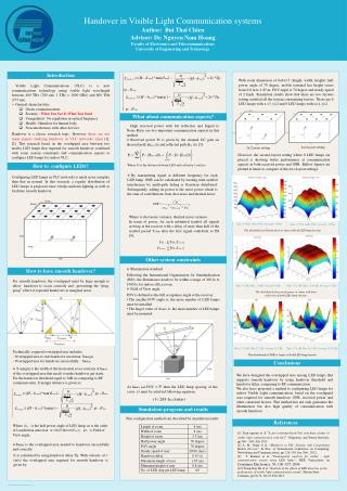
Handover in Visible Light Communication systems Author: Bui Thai Chien Advisor: Dr. Nguyen Nam Hoang Faculty of Electronics and Telecommunications University of Engineering and Technology Introduction With room dimension of 8x4x3.5 (length, width, height), half power angle of 70 degree, mobile terminal has height varies from 0.8 m to 1.85 m, FOV angle is 70 degree and steady speed of 2 km/h. Simulation results show that there are two layouts setting satisfied all the system constraining factors. Those are 6 LED lamps with x =3, y=2 and 8 LED lamps with x=4, y=2. • Visible Light Communications (VLC) is a new communications technology using visible light wavelength between 400 THz (780 nm; 1 THz = 1000 GHz) and 800 THz (375 nm). • General characteristics • Green communications • Security : What You See Is What You Send • Unregulated : No regulation in optical frequency • Health : Harmless for human body • Non-interference with other devices • Handover is a classic research topic. However, there are not many papers studying handover in VLC networks since [1], [2]. This research based on the overlapped area between two nearby LED lamps that required for smooth handover combined with some system constraints and communication aspects to configure LED lamps for indoor VLC. What about communication aspects? • High received power with fist reflection and Signal to Noise Ratio are two important communication aspects in this method. • Received power Pr is given by the channel DC gain on directed path and reflected path [3]: 4x2 layout setting 3x2 layout setting However, the second layout setting where 8 LED lamps are placed is showing better performance at communication aspects in both received power and SNR. Bellow figures are plotted at hmax to compare of this two layout settings. Where: D is the distance between LED and a detector’s surface How to configure LEDs? • By transmitting signal at different frequency for each LED lamp. SNR can be calculated by treating inter-symbol interference by multi-path fading is Gaussian distributed. Subsequently, adding its power to the noise power which is the sum of contributions from shot noise and thermal noise: Configuring LED lamps in VLC networks is much more complex than that in normal. In this research, a regular distribution of LED lamps is proposed since it helps uniform lighting as well as facilitate smooth handover. Where is shot noise variance, thermal noise variance. In terms of power, for each submitted symbol all signals arriving at the receiver with a delay of more than half of the symbol period Tsym after the first signal contribute to ISI [4]: Max: 1465lx, Min:369lx, Average: 1033lx Max: 1775lx, Min:522lx, Average: 1358lx The distributed of illumination at hmax of both LED lamp layouts Other system constraints • Illumination standard • Following the International Organization for Standardization (ISO), the illuminance needs to be within a range of 300 lx to 1500 lx for indoor office room. • Field of View angle • FOV is defined as the full acceptance angle at the receiver • The smaller FOV angle is, the more number of LED lamps must be installed • The larger value of h𝑚𝑎𝑥 is, the more number of LED lamps must be mounted How to have smooth handover? For smooth handover, the overlapped must be large enough to allow handover to occur correctly and preventing the “ping- pong” effect of repeated handovers at marginal areas. Max: 4.5dB, Min:-1.9dB, Average:3.0dB Max: 5.41 dB,Min: -0.44 dB, Average:4.2 dB The distributed of received power at hmax with first reflection of both LED lamp layouts A B Max: 57.8dB, Min:23.1dB, Average:33.1dB Max: 59.5 dB, Min:24.9 dB, Average:33.58 dB • Technically, required overlapped area includes: • Overlapped area to start handover execution: Smargin • - Overlapped area for handover successfully: Sdelay The distributed of SNR at hmax of both LED lamp layouts Conclusions • S margin is the width of the horizontal cross-sections at hmax of the overlapped area that needs to make handover get starts. For the handover threshold equal to 3dB as comparing to RF communication, S margin distance is given as: We have designed the overlapped area among LED lamps that supports smooth handover by using handover threshold and handover delay, comparing to RF communication. We also have proposed a method to configuring LED lamps for indoor Visible Light communication. based on the overlapped area required for smooth handover, SNR, received power and other constraint factors. This method has not only guarantee the illumination but also high quality of communication with smooth handover. At hmax and FOV = then the LED lamp spacing of the cross r1 must be satisfied following equation: Simulation program and results This configuration method can described by simulation results References Where is the half power angle of LED lamp, m is the order of Lambertian emission , is Field of View angle. [1] Tuan nguyen et al “A pre-scanning-based link switching scheme in visible light communication networks” Ubiquitous and Future Network, pp 366 – 369, July 2013 [2] A. M. Vegni et al, “Handover in VLC Systems with Cooperating Mobile Devices”, In Proc. of International Conference on Computing, Networking and Communications, pp. 126-130, Jan.-Feb., 2012. [3] T. Komine et al, “Fundamental analysis for visible - light communication system using LED lights”, IEEE Transactions on Consumer Electronics, 50, 100–107, 2004 [10] Trong-Hop Do el at, “Analysis of the effects of LED direction on the performance of visible light communication system", Photon NetwCommun, pp 60-72, Vol 25, Feb 2013. • Sdelay is the overlapped area needed to handover successfully and correctly. It is calculated by using handover delay Tp. With velocity of v (m/s) the overlapped area required for smooth handover is given by: