LEES
A VHF Resonant Boost DC/DC Converter. LEES. Justin Burkhart - Advisor: David Perreault Department of Electrical Engineering and Computer Science :. Project Goals. Improved Inverter. Completed Converter Design.

LEES
E N D
Presentation Transcript
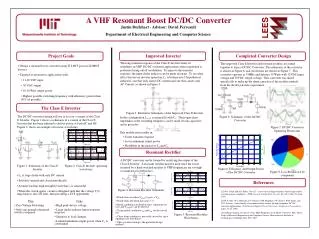
A VHF Resonant Boost DC/DC Converter LEES Justin Burkhart - Advisor: David Perreault Department of Electrical Engineering and Computer Science : Project Goals Improved Inverter Completed Converter Design The long transient response of the Class E Inverter limits its usefulness in VHF DC/DC converter applications where regulation is performed using on/off modulation. To improve the transient response, the input choke inductor can be made resonant. To see what effect this has on inverter operation, L1 is broken into 2 hypothetical inductors, one that only carries DC current and one that carries only AC Current, as shown in Figure 3. The improved Class E Inverter and resonant rectifier are joined together to form a DC/DC Converter. The schematic of the converter is shown in Figure 6, and waveforms are shown in Figure 7. This converter operates at 75MHz and delivers 15 Watts with 12VDC input voltage and 30VDC output voltage. This converter was tuned specifically to make up the shunt capacitor of the rectifier entirely from the diodes parasitic capacitance. • Design a resonant boost converter using TI LBC5 process LDMOS devices • Targeted at automotive applications with: • 11-16 VDC input • 30 VDC output • 10-20 Watt output power • Highest possible switching frequency with efficiency greater than 80% (if possible) The Class E Inverter Figure 3. Illustrative Schematic of the Improved Class E Inverter The DC/DC converter design will use at its core a variant of the Class E Inverter. Figure 1 shows a schematic of a varient of the Class E Inverter that has been adjusted to deliver power at both AC and DC. Figure 2. shows an example of inverter waveforms. Figure 6. Schematic of the DC/DC Converter In this configuration L1-AC is in parallel with C1. Their equivalent impedance at the switching frequency can be made it look capacitive and is given by: Figure 7. DC/DC Converter Operating Waveforms • This modification results in: • Faster transient response • Lover minimum output power • Flexibility in the choice of L1 and C1 Resonant Rectifier A DC/DC converter can be formed by rectifying the output of the Class E Inverter. A resonant rectifier must be used since the losses incurred by a hard switched rectifier at VHF frequencies are too high to maintain good efficiency. Figure 1. Schematic of the Class E Inverter Figure 2. Class E Inverter operating waveforms Figure 8. Efficiency and Output Power of the DC/DC Converter Figure 9. Loss Breakdown by component • L1 is large choke with only DC current • Switch is opened and closed periodically • Assume load has high enough Q such that io is sinusoidal • When the switch opens, circuit is designed such that the voltage V(t) rings back to zero DT later, thus providing a ZVS opportunity Vdiode(t) References Figure 4. Resonant Rectifier Schematic [1] N.O. Sokal and A.D Sokal. Class E – a new class of high-efficiency tuned single-ended switching power amplifiers. IEEE Journal of Solid-State Circuits, SC-10(3):168-176, June 1975. [2] W.A. Nitz, W.C. Bownam, F.T. Dickens, F.M Magalhaes, W. Strauss, W.B. Suiter, and N.G. Zeisses. A new family of resonant rectifier circuits for high frequency DC-DC converter applications. Third Annual Applied Power Electronics Conference Proceedings, pages 12-22, 1988. [3] Anthony Sagneri, Design of a Very High Frequency dc-dc Boost Converter, M.S. Thesis, Dept. of Electrical Engineering and Computer Science, Massachusetts Institute of Technology, Cambridge, MA, Feb. 2007 • Diode turns on when Vdiode(t) goes > Vout • Diode turns off when Io(t) goes < 0 • Initial conditions are known; thus, equations for Io(t) and Vdiode(t) can be derived • Using initial conditions ton and toff can be solved for • Close form solutions is not easily arrived at since equations are non-linear • Thus, rectifier tuning is the preferred design method Pros Cons • Zero Voltage Switching • Only one ground referenced switch is required • High peak device voltage • Large choke inductor limits transient response • Sensitive to load changes • Limited minimum output power when C1 is constrained Figure 5. Resonant Rectifier Waveforms