Download
1 / 104
1.09k likes | 1.41k Vues
J. McCalley. Double-fed electric machines – steady state analysis. Four configurations. We will study only this one, the DFIG. 2. Power Grid. DFIG. Rotor. DC Link. DC AC. AC DC. Basic concepts. Rotor is wound: it has 3 windings. Stator has three windings.

E N D
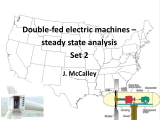
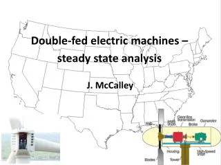
J. McCalley Double-fed electric machines – steady state analysis
Four configurations We will study only this one, the DFIG. 2
Power Grid DFIG Rotor DC Link DC AC AC DC Basic concepts Rotor is wound: it has 3 windings. Stator has three windings. Induction machine looks like a transformer with a rotating secondary (rotor). In DFIG, we will inject a voltage control signal via that converter. 3
Basic Concepts rotor (fs: 60 Hz, p: # of pole pairs) • Balanced voltages applied to stator windings provides a rotating magnetic field of speed • which induces an emf in the rotor windings according to • eind=induced emf in one conductor of rotor • v=velocity of conductor relative to stator flux rotation • B=stator magnetic flux density vector • L=length of conductor in direction of wire 4
Basic concepts Mechanical rad/sec We can manipulate to get: The induced rotor voltages have frequency of : Substitution into slip expression above yields: Observe three modes of operation: ωm< ωsωr>0s>0Subsynchronous operation ωm= ωsωr=0s=0Synchronous operation ωm>ωsωr<0s<0Supersynchronous operation 5
Per-phase steady-state model STATOR VOLTAGE EQUATION: at fs =stator voltage with frequency fs These quantities are referred to stator side. = emf in the stator windings with frequency fs = stator current with frequency fs =stator resistance =stator leakage reactance at fr ROTOR VOLTAGE EQUATION: These quantities are referred to rotor side, indicated by prime notation. =rotor voltage with frequency fr =induced emf in the rotor windings with frequency fr =induced rotor current with frequency fs =rotor resistance =rotor leakage reactance= 6
Application of Faraday’s Law allows the stator back emf and the induced rotor voltage to be expressed as: Ks, Kr: stator and rotor winding factors, respectively, which combine the pitch and distribution factors. Ns, Nr: number of turns of stator & rotor, respectively. fs, fr, frequency of stator & rotor quantities, respectively φm : magnetizing flux Referring quantities Solve both relations for φm and equate: But recall: The ratio Ks/Kr is normally very close to 1, therefore Define the effective turns ratio: Define the induced rotor voltage referred to the stator side: 7
We just derived that: (*) At a locked rotor condition (s=1), the device is simply a static transformer, and we have: Referring quantities This tells us it we want to move a voltage from rotor side to stator side, we multiply it by a=Ns/Nr. We can obtain similar relationships for currents and impedances, and so we define the rotor quantities referred to the stator according to: Rotor quantities are referred to the stator-side, indicated by unprimed quantities. Rr Rs jωrLσr Is jωsLσs Ir This is locked rotor condition (s=1), therefore ωr=ωs and Ers=Es Es 3 3 3 3 Ers Vs Vr 3 3 3 3 We can account for other slip conditions using ωr=sωs and from (*), aE’rs=sEs. 8
Rr Rs jsωsLσr Is jωsLσs Ir Es Referring quantities Ers=sEs Vs Vr Now write the rotor-side voltage equation (referred to stator): Divide by s and we get the following circuit: Rr/s The voltage on both sides of the xfmr is the same, therefore, we may eliminate the xfmr. .We represent a magnetizing inductance jωsLm in its place. Rs jωsLσr Is jωsLσs Ir 3 3 3 3 3 3 3 3 3 3 3 3 3 3 3 3 Es Es Vs Vr/s 9
Rr/s Rs Is jωsLσs jωsLσr Ir Referring quantities Es jωsLm Vs Vr/s 3 3 3 3 3 3 10
Rr/s Rs Is jωsLσs jωsLσr Ir Power relations Es jωsLm Vs Vr/s We modify the above circuit slightly in order to clearly separate slip-dependent terms from loss terms: 3 3 3 3 3 3 Change the circuit accordingly…. 11
Vr(1-s)/s Rr Rs Is jωsLσs jωsLσr Ir + - Power relations Rr(1-s)/s Es jωsLm Vr Vs It is possible to prove that the mechanical power out of the machine is the power associated with the slip-dependent terms R2(1-s)/s and Vr(1-s)/s. To do so, use: Power balance relation: where Ps and Pr are powers entering the machine through the stator & rotor windings, respectively, and Ploss,s and Ploss,r are the stator and rotor winding losses, respectively. Expressing the right-hand-terms of the power balance relation in terms of the above circuit parameters leads one to identify the slip-dependent terms as Pmech. 3 3 3 3 3 3 Knowing that the slip-dependent terms are those responsible for mechanical power, we may obtain the power expressions from the circuit, as on the next slide. 12
Pmech Veq= Vr(1-s)/s Rr Rs Is jωsLσs jωsLσr Ir + - Power relations Req= Rr(1-s)/s Es jωsLm Vr Vs Rotor current (Ir) direction is out of positive side of voltage source; therefore it supplies power to circuit. But a normal (positive) resistance Req always consumes power. So these two terms should be opposite sign. Defining Pmech>0 (see below) as motor mode implies Req term should be added and Veq term should be subtracted. 3 3 3 3 3 3 If Pmech>0the machine is delivering power through the shaft: MOTOR! If Pmech<0the machine is receiving power through the shaft: GEN! If 0<s<1Req term is positive Veq term is positiveSupplying P to cct If 0>s>-1Req term is negative Veq term is negativeConsuming P from cct. 13
Veq= Vr(1-s)/s Rr Rs Is jωsLσs jωsLσr Ir + - Req= Rr(1-s)/s A first torque expression Es jωsLm Vr Vs (p: # of pole pairs) Recall from slide 5: 3 3 3 3 3 3 and Therefore: 14
Veq= Vr(1-s)/s Rr Rs Is jωsLσs jωsLσr Ir + - Req= Rr(1-s)/s A second (equivalent) torque expression Es jωsLm Vr Vs Stator power: Stator voltage: Substitute Vs into Ps: 3 3 3 The middle two terms are purely imaginary, therefore: 3 3 3 First term is purely real, only the second term contains real and imaginary, therefore: 15
Veq= Vr(1-s)/s Rr Rs Is jωsLσs jωsLσr Ir + - Req= Rr(1-s)/s A second (equivalent) torque expression Es jωsLm Vr Vs Rotor power: Rotor voltage: Substitute Vr into Pr: 3 3 3 3 3 3 The middle two terms are purely imaginary, therefore: First term is purely real, only the second term contains real and imaginary, therefore: 16
Now substitute Ps and Pr into the power balance equation: A second (equivalent) torque expression Observe we have loss terms added and subtracted in the above, so they go away. Now consider what happens when you take the real part of a vector multiplied by j (or rotated by 90 degrees): ja a Observe that Re(ja) = - Im(a) Im(a) Re(ja) Therefore: 17
Let’s consider another vector identity: taking imaginary part of a conjugated vector: Observe that Im(a*) = - Im(a) A second (equivalent) torque expression a Im(a) Im(a*) a* Therefore: Recall: Recall: Therefore: 18
Two equivalent torque expressions Torque expression #1: Need rotor speed, rotor voltage and rotor current Torque expression #2: Need stator current and rotor current A third set of equivalent torque expressions follow…. 19
If we assume the magnetic core of the stator and rotor is linear, then we may express flux linkage phasors of each winding (stator winding and rotor winding, respectively): Mutual inductances Additional equivalent torque expressions Rotor winding Stator winding Self inductances ASIDE: Each self inductance is comprised of mutual and leakage according to: Therefore: From stator winding equation: From rotor winding equation: Choose one of these equations and substitute into torque expression #2…. 20
From stator winding equation: From rotor winding equation: Substitute into torque expression #2…. Additional equivalent torque expressions Using stator winding equation: Using rotor winding equation: Purely real Purely real 21
On slides 15 and 16, we derived the following relations for the power into the stator and rotor respectively: Subtracting losses from both sides, we obtain: Airgap and slip power This quantity is the power that flows from the stator terminals to the rotor (negative for generator operation). In other words, it is the power across the airgap. Therefore: This quantity is the power that is transferred from the grid to the rotor through the converter (negative when it is into the grid). It is called the slip power. Therefore: Bring out front the “s” in the slip power expression and use Re{ja}=-Im(a) (both): Use Im(a*) = -Im(a) on slip expression: The term 3Im{} in the slip power expression is Pairgap. Therefore: 22
So we just proved that: where Airgap and slip power Our power balance relation states: Therefore: Substituting we obtain Recall: Substituting: 23
On slides 15 and 16, we derived the following relations for the power into the stator and rotor respectively: If we neglect the stator losses (3RSIs2) and rotor losses (3RrIr2): Approximate relations between active powers Bring out front the “s” in the rotor power expression and use Re{ja}=-Im(a) (both): Use Im(a*) = - Im(a) on the rotor power expression The term 3Im{} in the rotor power expression is PS. Therefore: Recall the power balance relation: Neglecting losses: Substituting Pr expression: Recall: 24
Both Approximate Exact Active power relations - summary 25
Without losses With losses Power balance Pslip Pslip Pairgap Pairgap Ps Ps Pgrid Pr Pgrid Pr Ploss,r Ploss,s Pmech Pmech These figures assume proper sign convention (power flowing to the rotor is positive). 26
Generator modes For each mode, we may use the three relations to track the sign Ps, ωr, and Pr from the signs of Tem and s. For example, for mode 2, Tem<0Ps<0 and Tem<0, s<0 ωr<0Pr<0 Focusing on the generator modes, we observe the standard induction machine generating mode, supersynchronism, where ωm>ωs (mode 2). We also observe a subsynchronous mode (mode 3), where ωm<ωs, which is available to the DGIG as a result of the machine receiving power from the grid via the rotor circuit. 27
Recall the approximate relation Generator modes Operation must have |s|<1, so rotor power is always smaller than stator power. Mode 2 Pm= Pmech In fact, DFIGS always run within about -0.3<s<0.3. Therefore, the rating of the PE converter circuit need be only about 30% of the stator winding rating. Mode 3 These figures show actual flow direction for generator operation. They also neglect losses. 28
This figure assumes proper sign convention (power flowing to the rotor or into the stator is positive). Without losses Pslip Pairgap Ps Pgrid Pr Assume an operating condition such that Pmech=PWTrating. Then A question on rating Pmech For example, consider Pmech=PWTrating=-2 MW. In supersynchronous mode, with s=-0.3, Therefore stator winding must be rated for 1.5385 MW. But in the subsynchronous mode, s=+0.3, then Question: Does this mean that the stator of a 2 MW turbine must be rated for 2.8571? Answer: No. In subsynchronous mode, the mechanical power from the generator shaft is lower that that in the supersynchronous mode. If Pmech increases beyond a certain level, then machine speed increases into the supersynchronous mode. So above situation never occurs. We can obtain the maximum power in subsynchronous mode as: 29
Question: Since stator losses (3RSIs2) and rotor losses (3RrIr2) are always positive, and since we get sign changes with the numerical values of Pmech, Ps, and (sometimes) Pr, do the loss terms in the above equation need to have different signs for motor operation than for generator operation? That is, do we need to do the following? Question on sign of losses Motor operation: Generator operation: Answer: No. Our original equation applies for both motor & generator operation. Remember: Pmech is positive for motor operation; Ps, and Pr are positive when flowing into the device from the grid. It may help to think about the equation in two different, but equivalent forms. Motor operation: Generator operation: 50 = 45 +10 - 3 - 2 - 50 = - 55 + 3 + 2 30
In general, per-unitization enables inclusion of DFIGs within a system model. • It also facilitates identification of inappropriate data. Finally, a per-unitized voltage provides the ability to know how far it is from its nominal value (usually also the “normal” value) without knowing that nominal value. • The procedure is to choose three base quantities and compute other necessary base quantities. We will choose our base quantities as • rated rms line-to-neutral stator voltage, Vbase=|Vs|rated (rms volts); • rated rms stator line current, Ibase=|Is|rated (rms amperes) • rated stator synchronous frequency, ωbase= ωs,rated (rad/sec)) Per-unitization Then we compute: • Base impedance: • Base inductance: • Base flux: • Base speed: • Three-phase power base: • Base torque: 31
Once all base quantities are obtained, then per-unitization is easy: • Stator voltage in pu: Per-unitization – stator side • Stator current in pu: • Stator flux in pu: • Stator active power in pu: • Stator reactive power in pu: As usual, only the magnitude is transformed (angle remains unchanged). 32
Rotor voltage in pu: Per-unitization – rotor side For the rotor side, we use the same base quantities as on the stator side (with actual quantities referred to the stator side). • Rotor current in pu: • Rotor flux in pu: • Rotor active power in pu: • Rotor reactive power in pu: As usual, only the magnitude is transformed (angle remains unchanged). 33
Torque in pu: On the rotor side, we use the same base quantities as on the stator side (with actual quantities referred to the stator side). Per-unitization – torque, speed, R, L • Speed in pu: • Resistances in pu: Note that the resistances and inductances when expressed in pu are lower case. • Inductance in pu: As usual, only the magnitude is transformed (angle remains unchanged). 34
From slides 15, 16, we obtain voltage equations for stator and rotor circuits: which we rearrange by collecting terms in jωs: Voltage equations expressed in per unit From slide 20, we obtain the equations for stator and rotor flux linkages: (*) We recognize the flux linkage expressions in the voltage equations. Therefore: Now we can replace voltages, currents, and flux linkages with the product of their per-unit value and their base quantity, then the base quantities can be used to per-unitize the resistances and frequency to obtain: 35
Replace voltages, currents, flux linkages with the product of their pu value and their base quantity, then base quantities are used to per-unitize resistances and frequency to obtain: Voltage equations expressed in per unit Now consider the flux linkage equations: Replace currents and flux linkages with the product of their pu value and their base quantity, then base quantities are used to per-unitize inductances to obtain: Per-unitize one of the torque equations (#2) as follows: Per-unitize the power expressions to obtain: 36
Homework #3: This homework is due Monday, March 26. A. Using previous relations provided in these slides, derive the following torque expressions. Homework #3 (and identify σ) • B. Use Q = 3Im{VI*} and the equivalent circuit to derive reactive power expressions, in terms of Is and Ir for • The stator, Qs • The rotor, Qr • C. For each DFIG condition below, compute Pairgap and Pslip and draw the power flows similar to slide 28. • Pmech=-1 MW with s=+0.30 (subsynchronous operation). • Pmech=-1MW with s=-0.30 (supersynchronous operation). • D. Complete the table on the next slide (the boxed section) by computing the per-unit values of the indicated five resistances/inductances for the 2 MW machine. 37
Homework u (or a) Rs Lσs Lm R’r Lσr Rr Lσr Ls Lr Vbase Ibase Rs lσs lm rr lσr 38
We have developed the following relations: (1) Stator voltage equation (2) Rotor voltage equation (3) Stator winding flux equation Phasor diagrams for generator operation (4) Rotor winding flux equation Draw phasor diagram per below (CCW rotation is pos angle): Step 1: Draw Vs as reference (0°). Step 2: For gen, Qs>0, lag; for gen Qs<0, lead. Draw Is phasor. Step 3: Use (1) to draw the stator flux phasor λs: Step 4: Use (3) to draw the rotor current phasor Ir: Step 5: Use (4) to draw the rotor flux phasor λr: Step 6: …. Vs - Isrs Isrs Vs Is Ir=λs/lm – lsIs/lm lmIs λs/lm – lsIs/lm λr=lmIs+lrIr 39 λs= -j(Vs – Isrs) lrIr
Draw phasor diagram per below (CCW rotation is pos angle): Step 1: Draw Vs as reference (0°). Step 2: For gen, Qs>0, lag; for gen, Qs<0, lead. Draw Is phasor. Step 3: Use (1) to draw the stator flux phasor λs: Step 4: Use (3) to draw the rotor current phasor Ir: Step 5: Use (4) to draw the rotor flux phasor λr: Step 6: Use (2) to draw the rotor voltage phasor Vr: Phasor diagrams for generator operation jsλr, s>0, sub-sync Vr=Irrr+jsλr, s<0 super-syn Vr=Irrr+jsλr, s>0 Vs - Isrs Isrs Vs Irrr Is Ir=λs/lm – lsIs/lm lmIs jsλr, s<0 λs/lm – lsIs/Lm Observe that the angle of Vr is heavily influenced by the sign of s. λr=lmIs+LrIr λs= -j(Vs – Isrs) lrIr 40
Consider the circuit below, which is analogous to our stator winding circuit. At any operating condition, we may characterize the circuit as an impedance Z=R+jX=Z/_θ, as indicated. Then we may express the current according to Machine Question: How to know quadrant of Is? Observe that current angle is always negative of impedance angle, θi=-θ Z Z V V I I Lag Lag I I V V Z Z Lead Lead 41
The 2 MW DFIG given by the data on slide 38 is delivering, from the stator, rated load (2 MW) at rated voltage with zero stator reactive power in a 50 Hz grid. The slip is s=-0.25 (super-synchronous). Compute: (h) Rotor real power (i) Rotor reactive power (j) Total real power generated (k) Tem (d) Stator flux (e) Rotor current (f) Rotor flux (g) Rotor voltage (a) Synchronous speed (b) Line-to-neutral voltage (c) Line current Example Problem (a) Synchronous speed: Alternatively, the synchronous speed was given as 1500 rpm, therefore: (b) Line-to-neutral voltage: (c) Line current: (d) Stator flux 42
The 2 MW DFIG given by the data on slide 38 is delivering, from the stator, rated load (2 MW) at rated voltage with zero stator reactive power in a 50 Hz grid. The slip is s=-0.25 (super-synchronous). Compute: (h) Rotor real power (i) Rotor reactive power (j) Total real power generated (k) Tem (d) Stator flux (e) Rotor current (f) Rotor flux (g) Rotor voltage (a) Synchronous speed (b) Line-to-neutral voltage (c) Line current Example Problem (e) Rotor current This is the referred rotor current! We can obtain the actual rotor current from a (or u) =0.34: This phasor is at the rotor frequency, of fr=sfs=-0.25(50)=-12.5 Hz (f) Rotor flux (g) Rotor voltage Actual rotor voltage: 43
The 2 MW DFIG given by the data on slide 38 is delivering, from the stator, rated load (2 MW) at rated voltage with zero stator reactive power in a 50 Hz grid. The slip is s=-0.25 (super-synchronous). Compute: (h) Rotor real power (i) Rotor reactive power (j) Total real power generated (k) Tem (d) Stator flux (e) Rotor current (f) Rotor flux (g) Rotor voltage (a) Synchronous speed (b) Line-to-neutral voltage (c) Line current Example Problem (h) Rotor real power (i) Rotor reactive power (j) Total real power generated • Comments: • Pm must be larger in magnitude to supply losses This wind turbine’s rating should be 2.55 MW. The DFIG stator winding is rated for 2MW. 44
The 2 MW DFIG given by the data on slide 38 is delivering, from the stator, rated load (2 MW) at rated voltage with zero stator reactive power in a 50 Hz grid. The slip is s=-0.25 (super-synchronous). Compute: (h) Rotor real power (i) Rotor reactive power (j) Total real power generated (k) Tem (d) Stator flux (e) Rotor current (f) Rotor flux (g) Rotor voltage (a) Synchronous speed (b) Line-to-neutral voltage (c) Line current Example Problem (k) Tem 45
Rotor-side converter (RSC) is controlled so that it provides independent control of Tem and Qs. Let’s study the steady-state actions of this particular control function. Wind turbine control levels Level I: Regulates power flow between grid and generator. Level II: Controls the amount of energy extracted from the wind by wind turbine rotor. Level III: Responds to wind-farm or grid-central control commands for MW dispatch, voltage, frequency, or inertial control. 46
Level 1 control Assume DC bus voltage is controlled by grid-side converter (GSC) to a pre-determined value for proper operation of both GSC and RSC. We achieve control objectives by controlling rotor-side voltage. We control rotor voltage to achieve a specified torque and stator reactive power. This (open-loop) control not heavily used for DFIGs 47
Our objective here is, for a fixed stator voltage (fixed by the grid), and a desired torque Tem,ref and a desired stator reactive power Qs,ref, we want to determine the rotor voltage to make it so. We are also interested in the stator flux, stator current, rotor current, and rotor flux, and stator real power, as shown in the diagram below. Level 1 control 48
We draw the phasor diagram with stator flux as the reference (0 degrees). Here, the stator flux, denoted by ψs (instead of λs), is specified as the reference. We have identified particular angles in this phasor diagram. It is operating as a motor (current is almost in phase with voltage), and the stator is absorbing reactive power (Is has a negative angle relative to Vs, so Zmotor=Vs/Is has a positive angle, indicating it is inductive and therefore absorbing. Level 1 control 49
From voltage equation (slide 35): If we neglect drop across the stator resistance (it is typically very small), then: Level 1 control: Qs equation Substitute into the stator reactive power equation: Use Im(ja)=Re(a): From previous slide, note that ɣi is the angle by which Is leads λs , i.e., Substituting: Final equation for Qs: 50