Download
1 / 19
190 likes | 200 Vues
1. Figure 2.1 Latches, flip-flops, and registers. Figure 2.2 Operations of D latch and negative-edge-triggered D flip-flop. Figure 2.3 Register-to-register operation with edge-triggered flip-flops. Figure 2.4 State table and state diagram for a vending machine coin reception unit.

E N D
Figure 2.1 Latches, flip-flops, and registers. Computer Architecture Parhami
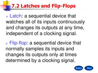
Figure 2.2 Operations of D latch and negative-edge-triggered D flip-flop. Computer Architecture Parhami
Figure 2.3 Register-to-register operation with edge-triggered flip-flops. Computer Architecture Parhami
Figure 2.4 State table and state diagram for a vending machine coin reception unit. Computer Architecture Parhami
Figure 2.5 Hardware realization of Moore and Mealy sequential machines. Computer Architecture Parhami
Table 2.1 State table for a JK flip-flop defined in Example 2.2. Computer Architecture Parhami
Figure 2.6 Hardware realization of a JK flip-flop (Example 2.2). Computer Architecture Parhami
Table 2.2 State table for a coin reception unit after the state assignment chosen in Example 2.3. Computer Architecture Parhami
Figure 2.7 Hardware realization of a coin reception unit (Example 2.3). Computer Architecture Parhami
Figure 2.8 Register with single-bit left shift and parallel load capabilities. For logical left shift, the serial data in line is connected to 0. Computer Architecture Parhami
Figure 2.9 Register file with random access and FIFO. Computer Architecture Parhami
Figure 2.10 SRAM memory is simply a large, single-port register file. Computer Architecture Parhami
Figure 2.11 Synchronous binary counter with initialization capability. Computer Architecture Parhami
Figure 2.12 Examples of programmable sequential logic. Computer Architecture Parhami
Figure 2.13 Determining the required length of the clock period. Computer Architecture Parhami
Figure 2.14 Synchronizers are used to prevent timing problems that might otherwise arise from untimely changes in asynchronous signals. Computer Architecture Parhami
Figure 2.15 Two-phase clocking with nonoverlapping clock signals. Computer Architecture Parhami