Download
1 / 6
60 likes | 77 Vues
In India, transportation through bridges plays a major role in channelizing the socio economic development. In the present paper, real case study has been considered for the construction of Railway over Bridge over Milan subway at Santacruz joining Western express Highway and SV Road Santacruz, with the sole aim to understand project management, micro planning, machinery and equipment required for the launching of girders by Cantilever Incremental Launching method. It is proved that the bridge construction by this method results in lesser consumption in time and economical for large projects. Manish Kotpalliwar | Nitesh Kushwaha ""Incremental Launching of the Steel Girders for Bridges"" Published in International Journal of Trend in Scientific Research and Development (ijtsrd), ISSN: 2456-6470, Volume-4 | Issue-2 , February 2020, <br><br>URL: https://www.ijtsrd.com/papers/ijtsrd30051.pdf<br><br>Paper Url : https://www.ijtsrd.com/engineering/civil-engineering/30051/incremental-launching-of-the-steel-girders-for-bridges/manish-kotpalliwar<br>

E N D
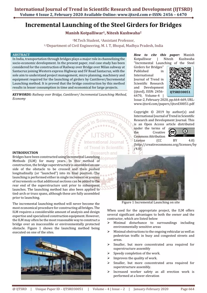
International Journal of Trend in Scientific Research and Development (IJTSRD) Volume 4 Issue 2, February 2020 Available Online: www.ijtsrd.com e-ISSN: 2456 – 6470 Incremental Launching of the Steel Girders for Bridges Manish Kotpalliwar1, Nitesh Kushwaha2 1M.Tech Student, 2Assistant Professor, 1,2Department of Civil Engineering, M. I. T, Bhopal,Madhya Pradesh, India ABSTRACT In India, transportation through bridges plays a major role in channelizing the socio-economic development. In the present paper, real case study has been considered for the construction of Railway over Bridge over Milan subway at Santacruz joining Western express Highway and SV Road Santacruz, with the sole aim to understand project management, micro planning, machinery and equipment required for the launching of girders by Cantilever/Incremental Launching method. It is proved that the bridge construction by this method results in lesser consumption in time and economical for large projects. KEYWORDS: Railway over Bridge, Cantilever/ Incremental Launching Method, Economy How to cite this paper:Manish Kotpalliwar | Nitesh "Incremental Launching of the Steel Girders for Bridges" Published in International Journal of Trend in Scientific Research and Development (ijtsrd), ISSN: 2456- 6470, Volume-4 | Issue-2, February 2020, pp.664-669, URL: www.ijtsrd.com/papers/ijtsrd30051.pdf Copyright © 2019 by author(s) and International Journal of Trend in Scientific Research and Development Journal. This is an Open Access article distributed under the terms of the Creative Commons Attribution License (CC (http://creativecommons.org/licenses/by /4.0) Kushwaha IJTSRD30051 BY 4.0) INTRODUCTION Bridges have been constructed using Incremental Launching Methods (ILM) for many years. In this method of construction, the bridge superstructure is assembled on one side of the obstacle to be crossed and then pushed longitudinally (or “launched”) into its final position. The launching is performed either in single increment or a series of increments so that additional sections can be added to the rear end of the superstructure unit prior to subsequent launches. The launching method has also been applied to tied-arch or truss spans, although these are fully assembled prior to launching. The incremental launching method will never become the most economical procedure for constructing all bridges. The ILM requires a considerable amount of analysis and design expertise and specialized construction equipment. However, the ILM may often be the most reasonable way to construct a bridge over an inaccessible or environmentally protected obstacle. Figure 1 shows the launching method being executed on one of the sites. Figure 1 Incremental Launching on site When used for the appropriate project, the ILM offers several significant advantages to both the owner and the contractor, which are listed below ?Minimal disturbance to surroundings including environmentally sensitive areas ?Minimal obstructions to the ongoing vehicular as well as pedestrian traffic in busy and congested streets and areas. ?Smaller, but more concentrated area required for superstructure assembly ?Speedy completion of the work. ?Improves the quality of work. ?Smaller, but more concentrated area required for superstructure assembly. ?Increased worker safety as all erection work is performed at a lower elevation @ IJTSRD | Unique Paper ID – IJTSRD30051 | Volume – 4 | Issue – 2 | January-February 2020 Page 664
International Journal of Trend in Scientific Research and Development (IJTSRD) @ www.ijtsrd.com eISSN: 2456-6470 The ILM can be used to construct a bridge over a wide range of challenging sites which feature limited or restricted access, including those with the following characteristics: ?Deep valleys ?Deep water crossings ?Railway Crossings ?Steep slopes or poor soil conditions making equipment access difficult CASE STUDY The sole aim of the project is to understand the site practices, micro-planning, design expertise, machineries and equipment’s required in the construction of ROB by incremental launching of steel girders for the railway span of ROB, with due consideration of railway norms and their standard operating procedures. Figure 2 shows the key plan of the site located near Santacruz Airport. The ROB is constructed in one of the busiest railway route i.e Santacruz in Mumbai. As shown in the key plan site is in the flying zone of Santacruz airport, there are height restrictions on use of cranes with long booms. Also, the site is surrounded with thick hutments, even site had no space between tracks to construct heavy temporary foundation, also train frequency is 1 train per every 2 minutes. Routine methods of Launching superstructure like Launching girders by heavy cranes or assembling the girders on adjacent span and pull it over the platform prepared on railway span by putting heavy supports between the tracks by using trolleys & tracks etc. So, site management decided to assemble the girder (whole carriage way) on the adjacent spans and pull it over the Railway span by incremental launching method one by one. The simple terminology was adopted to have more than double the weight on back side of girder (counter weight) than front cantilever portion of girder pulled over the Railway span as per following method statement a.Construction/erection of 3 nos. light temporary support/trestles between the railway tracks. b.Assembly of 1st three segments of @12m each total 36.m out of 5 segments (61.m) over the platform prepared on adjacent span P76 -P5A-P5. c.Pulling the girder partially by 12.0 m longitudinally at the railway span up to T1 (i.e. 1st pull) d.Joining/splicing the 4th segment of girder and pulling the whole assembly up to T2 location(2nd pull). e.Joining the 5th segment of the girder and pulling the girder to its final position at P6 (3rd Pull). FABRICATION The launching of the girder is performed in different stages. As the ROB spans between two piers P6 and P7, having total length of 61 m and maximum length of available steel plates for fabricating this box girder are of 13m hence, it was decided to divide the girder in 5 segments each of 12 m length for easy transportation and handling. The girders were prefabricated in workshop by the contractor M/S J Kumar Infra project sat M/S Geodesic Technologies Pvt. Ltd, Bangalore at their fabrication yard located at Bidar, Karnataka using most modern machines and equipment available in India. Cutting of plates by computerized programmed based SATO gas cutters and Robo Plasma cutting machines. drilling of holes by mobile electric drilling machine. Welding done by fully automatic SAW (submerse arc welding) machines, Semi-automatic SAW machines, FCAW (Flux Cored Arc Welding) etc. Quality control manual was prepared and accordingly strict quality control was adopted as per IRC/IS standards during the fabrication from testing of material to the fabrication of girders Railway span has two carriage ways, both carriage ways consists of 2 nos. flat plate camel back shaped steel box girder, each girder consists of 5 segments having total weight of 460 MT. Figure 2 Key Plan of site Keeping in view, the Railway Board’s policy decision and Western Railway’s requirements, MMRDA had proposed 61 m opening crossing over existing 7 main lines underneath. It was proposed to provide few steel girder spans on either side of Railway span over which complete assembly of 61 m span can be done and rolled over during minimum numbers of P&T blocks. Location of the ROB being close in the vicinity of Mumbai Airport due to which there was restrictions on height of ROB super structure. Details of the launching of railway span are given below. 1.Bridge length (overall)- 660 m 2.Length of the Railway span- 612 3.Bridge width-2 x 7.5 m 4.Type of foundation- Pile Foundation 5.Type of superstructure- MS Box Girder 6.Commencement of work – December 2011 7.Completion - May 2013 8.Tender cost – 42.24 Cr. 9.Contractor – M/S J Kumar Infraprojects Ltd. 10.PMC and Proof checking – M/S Bhobe Associates Pt Ltd. 11.Design Checking - Railway Design Cell 12.Proof checking (From Railways) – IIT Mumbai 13.Supervision (From Railway) –M/S RITES 14.Supervision (Fabrication)- M/S IRS Ltd. CONSTRUCTION METHODOLOGY: Individual length Cumulative length Total weight Cumulative weight 12.415M 12.415 M 12.00 M 24.415 M 12.00 M 36.415 M 12.00 M 48.415 M 12.415M 60.830 M Segment Pair No. 1st segment (N1 + S1) 2nd segment (N2+S2) 3rd segment (N3 + S3) 4th Segment (N4 + S4) 5th Segment (N5 + S5) 94.380 MT 91.677 MT 86.922 MT 91.622 MT 94.421 MT 94.380 MT 186.057 MT 272.997 MT 364.619 MT 459.052 MT @ IJTSRD | Unique Paper ID – IJTSRD30051 | Volume – 4 | Issue – 2 | January-February 2020 Page 665
International Journal of Trend in Scientific Research and Development (IJTSRD) @ www.ijtsrd.com eISSN: 2456-6470 Structural steel has been procured from Jindal Steel and Power Limited, Raigarh, Chattisgarh. Total requirement of the steel for both carriage was 925 MT. Entire steel is in the form of plate section ranging from 8 to 80 mm. Figure 3 and 4 show the fabrication work of steel girder and its transportation methodology being adopted to carry 12 x 4.4 x 1.0 m girder having total weight of 35 Tons, which could not have been carried as a regular transport goods and hence special permission was obtained for over dimensional consignment (ODC) from traffic department of Karnataka and Maharashtra states. Figures 3 and 4 show the prefabrication site selected for assembling the girder and transportation of 12 m span girder on the trailer. Figure 5 shows the arrangement made for launching of steel girders. Figure 3 Fabrication work at workshop Figure 5 Temporary arrangements on site Deck slabs over 2 non-Railway adjacent spans (P5 TO P5A and P5A to P6) at west end were provided to facilitate bolted/welded connections of proposed assembly and rolling bed for Railway span. Assembly /rolling bed was provided over non-Railway spans consisting of ISMBs, ISMCs, ISAs and plates duly prefabricated and connected by bolting /welding at site over non-Railway span. Catwalk with railing was also provided for safe movement of inspecting officials of various agencies. Due to constraint of curvature at both ends of Railway span, provision of full length of 61m bed was not possible to meet the total requirements. By providing additional column at North side of non-Railway span, total length of bed of 46.5 m could be achieved. Assembly of super structure – Sequence of Assembly Assembly No. Length 12.415 12.00 180-ton capacity hydraulic crane was placed at west end beyond rolling platform so as to handle segments/cross girders at adequate working radios to lift and swing 50-ton load. Assembly of leading pair of segments – (N1/S1) Segment N1 was placed over assembly bed. ISMBs struts were provided on either ends both sides to avoid overturning. All 9 cross girders were connected to segment N1 and bolted. Segment S1 was picked up by crane and was gradually pushed inside so that free ends of all cross girders are properly housed in over segment S1. The total assembly was jacked up on 100-ton hydraulic jacks and 100-ton capacity skid rollers were provided underneath the bottom Figure 4 Transportation of carriage way Pre-Launching arrangements& their testing a.Three temporary supports/trestles (T1, T2 and T3) were constructed in between railway tracks to support the load of box girders. Pairs of skid rollers having 200- ton capacity were provided over three trestles for rolling action. b.Detailed launching scheme was made and got approved from Railway department. c.TWO (traffic work order) having minute to minute details of planning of launching has been prepared and got it approved from railway department. d.Provision of Non-Railway steel girder spans at either side of Railway span were provided to facilitate assembly and rolling of Railway span was planned. e.All the launching equipment like winch machines, jacks, reversible pulling arrangement, load carrying capacity of temporary support caring maximum load (T1), sliding rollers, guiding rollers etc. were checked and tested. N1-S1 N2-S2 N3-S3 N4-S4 N5-S5 12.00 12.00 12.415 @ IJTSRD | Unique Paper ID – IJTSRD30051 | Volume – 4 | Issue – 2 | January-February 2020 Page 666
International Journal of Trend in Scientific Research and Development (IJTSRD) @ www.ijtsrd.com eISSN: 2456-6470 flanges of both main girders at approx 6 m apart. 12.410 m assembly was then pulled/ pushed forward towards east end by 20 ton electrically operated winches by 13m over skid rollers. This operation has made the free area of 13 m available for assembling second pair of segments –(N2/S2). Figure 6 shows the launching of leading girder on the temporary arrangements on site. Figure 7 Assembly of second pair of segments – (N2/S2) Assembly of middle pair of segments –(N3/S3) Segment N3 was placed on assembly bed over rollers duly locked and with wooden packing on top. Segment S3 was picked up by crane and was gradually pushed inside so that free ends of all cross girders are properly housed in over segment S3 and spliced to N2/S2 with HSFG fasteners. Now after joining this assembly, with the total length of 36.415mgirder is ready over skid rollers for partial launching (1st Launch) Figure 8Assembly of middle pair of segments – (N3/S3) Rolling Phase 1 After placing all the three segments, there was not enough space left to place fourth and fifth girder and hence, rolling of first phase of 12.0 M i.e. up to temporary support T1 was performed by pushing the segments in longitudinal direction across the railway span as shown in figure 9. On arrival of the leading end on the support T1, it was jacked up with 2/200-ton capacity hydraulic jacks so that deflected leading end could be raised and stool and skid rollers were provided. Figure 10 shows the rolling of leading span girder on first temporary Trestle T1. Figure 6 Assembly of leading pair of segments with rolling bed Assembly of second pair of segments –(N2/S2) Segment N2 was placed on assembly bed over rollers duly locked and with wooden packing on top. 42 mm thick packing was provided under the junction of bottom flanges of N1 and N2. Segment S2 was picked up by crane and was gradually pushed inside so that free ends of all cross girders are properly housed in over segment S2. For splicing of Segments N1-N2 & S1-S2 HSFG Fasteners of M 36 /10.8 grade were provided in all 4 web splices and over flange splices. Full assembly with the length of 24.415 m was then pulled/ pushed forward towards east end by 20 ton electrically operated winches by 13m over skid rollers. This operation has made further free space having length 13 m available behind, for assembly of third pair of segments. Figure 7 shows the launching of second segment (N2/S2). Figure 10 Rolling of leading end girder over trestle (T1) @ IJTSRD | Unique Paper ID – IJTSRD30051 | Volume – 4 | Issue – 2 | January-February 2020 Page 667
International Journal of Trend in Scientific Research and Development (IJTSRD) @ www.ijtsrd.com eISSN: 2456-6470 Rolling Phase II Remaining two segments of girders i.e. (N4/S4 and N5/S5) were placed on the platform and spliced with the assembly one by one in the similar fashion as done for first three segments, with joining this assembly total length of full girder assembly became 60.830 M. In this phase incremental /cantilever rolling of girder was performed in longitudinal direction from support T1 to Support T2 across the railway span. On arrival of the leading end on the support T2, it was jacked up with hydraulic jacks so that deflected leading end could be raised and stool and skid rollers were provided. During 1strolling phase, it was observed that paint film over the rolling surface of the bottom flange got peeled off from surface due to heavy friction and entered skid roller assembly. This has adversely affected lubrication status of roller assembly and friction level increased. Semi dry condition of roller assembly has also affected the smooth performance of rollers. To overcome this problem, continuous flow of lubricant into the roller assembly was maintained during entire rolling operation. On introduction of the system, entire rolling was very smooth with exceptions. Figure 11 shows the launching of girders in rolling phase II. ton hydraulic jacks on P6 and skid roller stools, skid rollers, guide roller assembly on T1 and skid rollers over P6 were removed. The fully launched carriage way super structure was lowered on 4 bearing points on P6 and P7 over crib of hard wood packings. Two additional supports were also provided under bearings cross girders at P6 and P7. Figure 12 shows the final rolling phase of the steel girders. Figure 12 Rolling phase III Launching of 2nd carriage way – The second carriage-way having all the parameters same as 1st carriage way also launched in the same fashion. Bearings Before final lowering of girders, all four bearings ends were precisely aligned over the bed blocks and super structure was made to rest over bearings. On total satisfaction of all Inspection Agencies, all bearings were welded to the bottom flanges from underside. Figure 13 shows the placement of bearing on the supports of the bridge. Bearings Provision of Pot PTFE Bearings were made as approved at all four ends as detailed below- South girder East end P7 (South) Transverse West end P6 (South) Free North Girder East end P7 (North) Fixed West end P6 (North) Longitudinal Figure 11 Rolling Phase II Rolling phase III Before pulling commenced, skid roller locks and wooden packings were removed after jacking the leading end and assembly placed over rollers. On completion of third and final phase of rolling, the leading end has reached over P7. Centre of Jacking cross girder (Bearing cross girder) of segment assembly of N1/S1 was aligned with the center of grillage provided over P7 and leading end was jacked up with 2/200-ton hydraulic jacks and skid roller stools, skid rollers and guide roller assembly over T2 and T 3 were removed. Trailing end of assembly was jacked with 2/200- Figure 13Bearings @ IJTSRD | Unique Paper ID – IJTSRD30051 | Volume – 4 | Issue – 2 | January-February 2020 Page 668
International Journal of Trend in Scientific Research and Development (IJTSRD) @ www.ijtsrd.com eISSN: 2456-6470 6.Launching is very easy on the water bodies in comparison to other methods of construction, because few or no temporary supports requirement. 7.Whereas railway traffic is not disturbed by launching with this method, this method is very useful in speedy completion of ROBs. 8.Time required for the construction of Major River Bridges, bridges at deep valleys, forest areas, sea bridges, flyovers at busy crossings & congested areas etc. is very mech reduced by using this method. 9.Due to on time completion of project, it save abnormal variations in the project cost & consequent losses to the contractor which finally resulted in disputes/ litigation between department and contactor. So, it will save cost, time & disputes. Figure 14 shows the complete view of Milan Bridge at Santa Cruz Railway station, which was one of the major ROB projects, completed within the stipulated time without disturbing the existing railway traffic. REFERENCES [1]Zellner and Svensson, “Incremental Launching of Structures”, Journal of Structural Engineering, 109 (2), 520-537, 1983. Figure 14 Completed View of Milan Road Over Bridge CONCLUSION: 1.Incremental launching is a very safe, fast & time bound method of launching of superstructure. 2.No major design changes are required in the superstructure for the launching arrangements. 3.Since superstructure is fabricated/casted at fabrication yard/precast yard and only assembling & launching is done at site, so the space required at site for construction activity is very less. 4.Quality control of the highest standards can be maintained since fabrication/casting is done at fabrication/casting yard under controlled conditions. 5.Since launching work can be done in night hours, Therefore very minimal obstruction to the ongoing vehicular & pedestrian traffic. [2]Per Granath, “Distribution of Support reaction against steel girder on a launching shoe", Journal of Constructional Steel Research, 47(3), 245-270, 1998. [3]Sasmal S, Ramanjaneyulu K, Srinivas V and Gopalkrishna S, “Simplified methodology for analysis and studies on behaviour of incrementally launched continous bridges”, Structural Engineering and Mechanics, 17(2), 245-266, 2004. Computational [4]Xu R, Shao B, “New Beam Element for Incremental launching of Bridges”, Journal of Bridge Engineering, 17(5), 822-826, 2011. [5]Granata M, Margiotta P, Arici M, “A Parametric study of Curved incrementally launched bridges”, Engineering Structures, 49, 373-384, 2013. @ IJTSRD | Unique Paper ID – IJTSRD30051 | Volume – 4 | Issue – 2 | January-February 2020 Page 669