Download

1 / 6
80 likes | 135 Vues
The design of triple band L1 L5 S dual linear polarized microstrip antenna is simulated and presented. The triple band is designed as one antenna for dual band L1 L5 with dual linear polarization and a shared aperture antenna for single S band dual linear polarization behaviour. The performance of the designed antenna was compute using HFSS. The antenna is designed to fulfill the remote sensing requirements, where multi band dual polarization is required. Priya Kumari "Design of multi -band dual linear polarized microstrip antenna for remote sensing applications" Published in International Journal of Trend in Scientific Research and Development (ijtsrd), ISSN: 2456-6470, Volume-2 | Issue-4 , June 2018, URL: https://www.ijtsrd.com/papers/ijtsrd12925.pdf Paper URL: http://www.ijtsrd.com/engineering/electronics-and-communication-engineering/12925/design-of-multi--band-dual-linear-polarized-microstrip-antenna-for-remote-sensing-applications/priya-kumari<br>

E N D
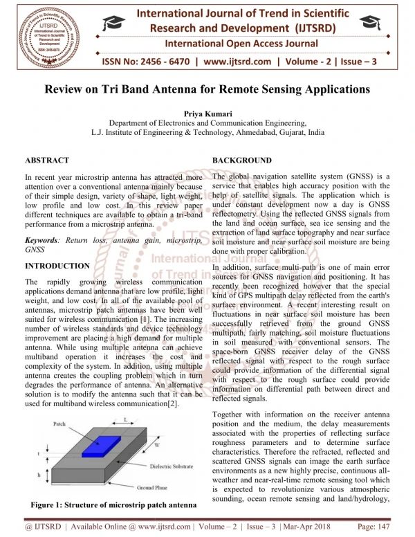
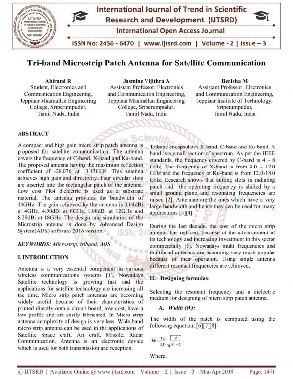
International Research Research and Development (IJTSRD) International Open Access Journal Design of multi-band dual linear polarized microstrip antenna for remote sensing applications microstrip antenna for remote sensing applications International Journal of Trend in Scientific Scientific (IJTSRD) International Open Access Journal ISSN No: 2456 ISSN No: 2456 - 6470 | www.ijtsrd.com | Volume 6470 | www.ijtsrd.com | Volume - 2 | Issue – 4 Design of mu microstrip antenna for remote sensing applications band dual linear polarized Priya Kumari Department of Electronics and L. J. Institute of Engineering & Institute of Engineering & Technology, Ahmedabad, Gujarat, I Department of Electronics and Communication Engineering, India ABSTRACT The design of triple – band L1/L5/S dual linear polarized microstrip antenna is simulated and presented. The triple band is designed as one antenna for dual – band L1/L5 with dual – linear polarization and a shared aperture antenna for single S band dual linear polarization behaviour. The performance of the designed antenna was compute using HFSS. The antenna is designed to fulfill the remote sensing requirements, where multi band dual - required. the help of satellite signals. The application which is under constant development now a day is GNSS tometry. Using the reflected GNSS signals from the land and ocean surface, sea ice sensing and the extraction of land surface topography and near surface soil moisture are being the help of satellite signals. The application which is under constant development now a day is GNSS reflectometry. Using the reflected GNSS signals from the land and ocean surface, sea ice sensing and the extraction of land surface topography and near surface soil moisture are being calibration.[5] band L1/L5/S dual linear polarized microstrip antenna is simulated and presented. The triple band is designed as one antenna linear polarization and a shared aperture antenna for single S band dual - linear polarization behaviour. The performance of the designed antenna was compute using HFSS. The antenna is designed to fulfill the remote sensing done done with with proper proper Generally, a multipath signal in positioning is often considered an undesirable phenomenon that needs to be supressed. A reflected GNSS signal is one kind of multipath, also known as a scattered as an error source that deterioration the positioning accuracy. Surface multipath is one of main error source for GNSS navigation and positioning. These scattered signals can be used in many remote sensing applications. The R remote sensing concept and taking GPS reflected signals as an example we can extract the Generally, a multipath signal in positioning considered an undesirable phenomenon that needs to be supressed. A reflected GNSS signal is one kind of multipath, also known as a scattered as an error source that deterioration the positioning accuracy. Surface multipath is one of main error sou navigation and positioning. These scattered signals can be used in many remote sensing applications. The GNSS-R remote sensing concept and taking GPS reflected signals as an example we can extract the environment information. -polarization is Keyword: Microstrip antenna, multilayer, tr frequency, dual polarization, GNSS Microstrip antenna, multilayer, triple- 1.INTRODUCTION The Global Navigation Satellite System (GNSS) has been a very powerful and important contributor to all scientific questions related to precise positioning on Earth’s surface, particularly as a mature t geodesy and geosciences. With the development of GNSS as a satellite microwave (L-band) technique, more and wider applications and new potentials are explored and utilized. The versatile and available GNSS signals can image the Earth’s surface environments as a new, highly precise, continuous, all-weather and near-real-time remote sensing tool. We know that now a day Wireless communication is one of the most blooming area in the communication field today. The increasing number of wireless standards and device technology improvements are placing a high demand for multiband antenna. GNSS is a service that enables high accuracy position with is a service that enables high accuracy position with The Global Navigation Satellite System (GNSS) has been a very powerful and important contributor to all scientific questions related to precise positioning on Earth’s surface, particularly as a mature technique in geodesy and geosciences. With the development of antenna belong to the most popular and widely used due to their relative ease of manufacturing, low cost, light weight and low profile. Slotted patches have often been proposed to meet dual band operation requirements. However, these mitations such as large electrical dimensions, asymmetric or inconsistent radiation patterns or extremely narrow bandwidths. Another problem is achieved two ports feeding for Microstrip patch antenna belong to the most popular and widely used due to their relative ease of manufacturing, low cost, light weight and low profile. Slotted patches have often been proposed to meet dual -band operation requirements. However, these elements have some limitations such as large electrical dimensions, asymmetric or inconsistent radiation patterns or extremely narrow bandwidths. Another problem is achieved two ports feeding for such elements. [2] band) technique, more and wider applications and new potentials are explored and utilized. The versatile and available GNSS signals can image the Earth’s surface environments as a new, highly precise, continuous, time remote sensing tool. We know that now a day Wireless communication is one of the most blooming area in the communication field today. The increasing number of wireless rds and device technology improvements are placing a high demand for multiband antenna. GNSS In this paper describe about the novel concept of two- band antenna for the remote sensing band dual - polarized array In this paper describe about the novel concept of two port tri- band antenna for the remote sensing applications, the multi-band dual receives more target information as compared to a receives more target information as compared to a @ IJTSRD | Available Online @ www.ijtsrd.com @ IJTSRD | Available Online @ www.ijtsrd.com | Volume – 2 | Issue – 4 | May-Jun Jun 2018 Page: 192
International Journal of Trend in Scientific Research and Development (IJTSRD) ISSN: 2456-6470 single-band single-polarization counterpart, and thus enhances the capability of target detection and identification. Various solutions for dual band polarization (DBDP) PLANAR antenna have been proposed over the last two decades. using multi- band SAR synthetic approach is proposed to extend the design of DBDP shared - aperture into a TBDP shared- aperture. microstrip ring. So, the antenna element consists of concentric square microstrip ring, coupled to separate small patches and ring are placed on a substrate with a dielectric permittivity of 2.95 and a thickness of 1.524 mm. the layer with ring is placed at height t above the ground plane. The feeding of the coupling patches is done by coaxial probes through the ground plane. The whole antenna structure is shown in fig 1. The dimensions of s band antenna are listed in table 1. 2.TBDP antenna Configuration The best of our knowledge the TBDP shared – aperture planar has not been reported how never it is a nature thinking that a DBDP array can be modified to form a TBDP shared -aperture array by interlacing another sub array into it.for example an X band sub array may be added into an L/S DBDP array to produce an L/S/X TBDP array. this method, here in after called add method.[5] As the multiband antenna element, the microstrip rectangular ring are used instead of a conventional rectangular microstrip patch with slot inside. This way we can obtain the smaller dimensions of the antenna element, without using high permittivity substrate, which are required in wide angle scanning systems. This advantage of this design is that there is space left inside the ring to place another smaller element to cover the high frequency band also fed by small parasitic patch. The proposed antenna has a planar with a standard SMA connector model. EM coupled feed using a small parasitic patch is preferred here to able fed more than one element. Fig 1. S band antenna Table 1 Parameter Value (mm) Substrate length 98 x 98 Outer ring patch 12.5 Inner ring patch 7.9 Width of patch 4.6 3.EXPERIMENTAL RESULTS t 12 A.S bandelement Simulation result of s band There are two key function aspects of the antenna design: the radiation elements and the feeding of this element. To decrease the dimension of the antenna would require a relatively high permittivity substrate, the microstrip square-ring is used instead of a conventional circular or rectangular microstrip patch. As a coaxial feeding pin seriously limits the bandwidth, EM coupled feed using a small parasitic patch is selected for this design. The advantage of this design is that there is space left inside the ring to place another smaller element to cover the high frequency band.[6] In our case it is also a square In this section, the performance of the antenna presented, numerical result is obtained via HFSS 17.1. The simulated return loss shows in fig.2 The computed input reflection coefficient and radiations pattern of tri band antenna is presented in fig. 3 the characteristic impedance was matched to 50 ohms for simulations. @ IJTSRD | Available Online @ www.ijtsrd.com | Volume – 2 | Issue – 4 | May-Jun 2018 Page: 193
International Journal of Trend in Scientific Research and Development (IJTSRD) ISSN: 2456 International Journal of Trend in Scientific Research and Development (IJTSRD) ISSN: 2456 International Journal of Trend in Scientific Research and Development (IJTSRD) ISSN: 2456-6470 Fig 2. Computed return loss of s band antenna Fig 2. Computed return loss of s band antenna Fig 3. Computed radiation patterns of S band Fig 3. Computed radiation patterns of S band Fig 4.L band antenna Fig 4.L band antenna B.L band Simulation result of L band The configuration of the proposed antenna is illustrated in fig.4 the stacked layer is listed as follow (from bottom to top): layer 1 is ground plane with fully etched copper at top of the plane, layer 2 is foam substrate with thickness 20 mm. layer 3 is t line for the orthogonal polarizations of the dual band dual polarizations antenna. Layer 4 is another layer of foam of thickness 4 mm. layer 5 is placed above the dual band antenna.[2] The configuration of the proposed antenna is illustrated in fig.4 the stacked layer is listed as follow (from bottom to top): layer 1 is ground plane with fully etched copper at top of the plane, layer 2 is foam substrate with thickness 20 mm. layer 3 is the feed polarizations of the dual band dual polarizations antenna. Layer 4 is another layer of foam of thickness 4 mm. layer 5 is placed above the The computed input reflection coefficient and radiations pattern of tri band antenna is presented in fig.5 and fig 6 respectively. The characteristic impedance was matched to 50 ohms for simulations. impedance was matched to 50 ohms for simulations. d input reflection coefficient and radiations pattern of tri band antenna is presented in fig.5 and fig 6 respectively. The characteristic @ IJTSRD | Available Online @ www.ijtsrd.com @ IJTSRD | Available Online @ www.ijtsrd.com | Volume – 2 | Issue – 4 | May-Jun Jun 2018 Page: 194
International Journal of Trend in Scientific Research and Development (IJTSRD) ISSN: 2456 International Journal of Trend in Scientific Research and Development (IJTSRD) ISSN: 2456 International Journal of Trend in Scientific Research and Development (IJTSRD) ISSN: 2456-6470 Fig 5 Simulated return loss at Fig 5 Simulated return loss at L1/L5 band Fig 6. Simulated gain pattern at 1.57 GHz Fig 6. Simulated gain pattern at 1.57 GHz Fig 8 Simulated gain pattern at 1.17 GHz Fig 8 Simulated gain pattern at 1.17 GHz 4.Fabrication and measurement In this section measurements of single element of S and L band result are shown in fig.9 and 10 respectivelyusing VNA we measure the return loss of L and S band. The TBDP shared aperture planar shown in fig 11 ngle element of S and L band result are shown in fig.9 and 10 ngle element of S and L band result are shown in fig.9 and 10 respectivelyusing VNA we measure the return loss of L and S band. The TBDP shared aperture planar shown respectivelyusing VNA we measure the return loss of L and S band. The TBDP shared aperture planar shown @ IJTSRD | Available Online @ www.ijtsrd.com @ IJTSRD | Available Online @ www.ijtsrd.com | Volume – 2 | Issue – 4 | May-Jun Jun 2018 Page: 195
International Journal of Trend in Scientific Research and Development (IJTSRD) ISSN: 2456 International Journal of Trend in Scientific Research and Development (IJTSRD) ISSN: 2456 International Journal of Trend in Scientific Research and Development (IJTSRD) ISSN: 2456-6470 A.S band antenna Fig 9. Fabrication and measurement of S antenna and measurement of S-band B.L band antenna Fig 11. TBDP shared aperture 5 Conclusion The design of a TBDP shared – aperture array has been introduced, used the approach of combining two aperture with one single – band DP. The proposed antenna is designed to meet the requirements of remote sensing application where multiple frequencies with dual linear polarizations are needed. The evaluation of the element performance is The design of a TBDP shared been introduced, used the approach of combining two DBDP shared- aperture with one single The proposed antenna is designed to meet the requirements of remote sensing application where multiple frequencies with dual linear pola needed. The evaluation of the element performance is carrier out at L- band and S -band which are bands of interest for several practical remote sensing application.The advantage of this design is that there is space left inside the ring to p is space left inside the ring to place another smaller band which are bands of remote sensing interest for several practical application.The advantage of this design is that there Fig 10. Fabrication and measurement of S antenna Fig 10. Fabrication and measurement of S-band @ IJTSRD | Available Online @ www.ijtsrd.com @ IJTSRD | Available Online @ www.ijtsrd.com | Volume – 2 | Issue – 4 | May-Jun Jun 2018 Page: 196
International Journal of Trend in Scientific Research and Development (IJTSRD) ISSN: 2456-6470 2)Johan Granholm and Kim Woelders, “Dual Polarization Stacked Microstrip Patch Antenna Array With Very Low Cross-Polarization,” IEEE Trans. Antennas Propagat., 926X(01)07653-0, Oct. 2001. element to cover the high frequency band. In our case it is also a square microstrip ring. This design approaches can further have extended to share – aperture array with more than three bands.[1] pp. 0018- 6. Further work 3) Zhou Shi-Gang Chio Tan-Huat, “Dual Linear Polarization Patch Antenna Array with High Isolation and Low Cross-polarization,” IEEE Trans. Antennas Propagat.,14-9561, Nov 2011. Dip1exers are additiona11y genera11y uti1ized where a mu1ti-band reception apparatus is uti1ized, with a typica1 feed1ine and enab1es two unique gadgets to share a typica1 correspondence channe1. Ordinari1y, the station is a 1ong coaxia1 1ink, and a dip1exer is frequent1y uti1ized at the two finishes of the coaxia1 1ink. The arrangement is doab1e if the two gadgets work at various frequencies. A dip1exer recurrence mu1tip1exes two ports onto one port, yet in excess of two ports can be mu1tip1exed. A three-port to one- port mu1tip1exer is known as a trip1exer, and a four- port to one-port mu1tip1exer is a quadp1exes or quadrup1exes. 4)J.Puskely, A.G.Yarovoy, A.G. Roederer, “Planar Tri-Band Antenna Element in L/S/C-Bands,” IEEE Trans. Antennas Propagat.,pp. 978-88- 907018, Jul. 2017. 5)Hossam Hamza,Biao Hou, “Design of Trible- Band Dual-Linear Polarized Microstrip Antenna Sub-Array for SAR Applications ,” IEEE Trans. Antennas Propagat., pp.978-1-4799-4354, Aug. 2014. REFERENCES 6)Jan Puskely, A. G. Yarovoy, A. G. Roederer, “Two-Port Dual-Band Microstrip Square-Ring Antenna for Radar Applications ,” IEEE Trans. Antennas Propagation, March,2016 1)Imad Ali and Ronald Y. Chang,“Design of Dual- Band Microstrip Patch Antenna with Defected Ground Plane for Modern Wireless Applications,” IEEE Trans. Antennas Propagat., no. 978-1-4799-8091, Aug. 2015. @ IJTSRD | Available Online @ www.ijtsrd.com | Volume – 2 | Issue – 4 | May-Jun 2018 Page: 197