Download
1 / 6
60 likes | 90 Vues
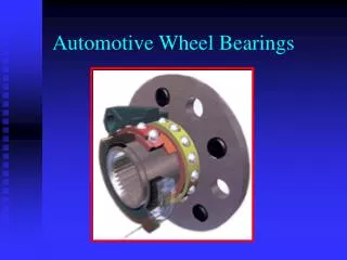
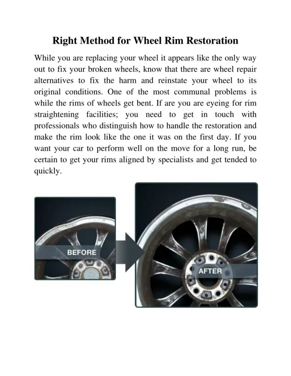
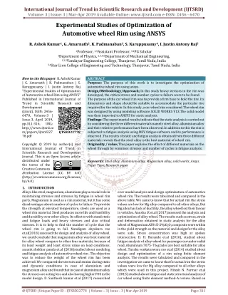
Purpose The purpose of this work is to investigate the optimization of automotive wheel rim using ansys. Design Methodology Approach In this study heavy stresses in the rim was developed, the critical stress and number cycles to failure were to be found. The purpose of the car wheel rim was to provide a firm base to hold the tire .Its dimensions and shape should be suitable to accommodate the particular tire required for the vehicle .In this study ,a car wheel rim considered .The wheel rim was designed by using modeling software SOLID WORKS V13.The solid model was then imported to ANSYS for static analysis. Findings The experimental results indicate that the static analysis is carried out by considering the three different materials namely steel alloy, alluminium alloy and their relative performance have been observed .In addition to this the rim is subjected to fatigue analysis using MSV fatigue software and its performance is observed .The results of static and fatigue analysis obtained from three different materials reveals that the steel alloy is the best material of wheel rim. Originality value This paper explains the effect of different materials on the wheel through by vonmises stresses and number of cycles in fatigue analysis. R. Ashok Kumar | G. Amarnath | K. Padmanaban | S. Karuppusamy | I. Justin Antony Raj "Experimental Studies of Optimization of Automotive wheel Rim using ANSYS" Published in International Journal of Trend in Scientific Research and Development (ijtsrd), ISSN: 2456-6470, Volume-3 | Issue-3 , April 2019, URL: https://www.ijtsrd.com/papers/ijtsrd22778.pdf Paper URL: https://www.ijtsrd.com/engineering/mechanical-engineering/22778/experimental-studies-of-optimization-of-automotive-wheel-rim-using-ansys/r-ashok-kumar<br>

E N D
International Journal of Trend in Scientific Research and Development (IJTSRD) Volume: 3 | Issue: 3 | Mar-Apr 2019 Available Online: www.ijtsrd.com e-ISSN: 2456 - 6470 Experimental Studies of Optimization of Automotive wheel Rim using ANSYS R. Ashok Kumar1, G. Amarnath2, K. Padmanaban3, S. Karuppusamy4, I. Justin Antony Raj5 1Professor, 2,5Assistant Professor, 3,4PG Scholar 1Department of Physics, 2,3,4,5Department of Mechanical Engineering, 1,2,5Vandayar Engineering College, Thanjavur, Tamil Nadu, India 3,4Star Lion College of Engineering and Technology, Thanjavur, Tamil Nadu, India How to cite this paper: R. Ashok Kumar | G. Amarnath | K. Padmanaban | S. Karuppusamy | I. Justin Antony Raj "Experimental Studies of Optimization of Automotive wheel Rim using ANSYS" Published in International Journal of Trend in Scientific Research and Development (ijtsrd), ISSN: 2456- 6470, Volume-3 | Issue-3, April 2019, pp.311-316, URL: http://www.ijtsrd.co m/papers/ijtsrd227 78.pdf Copyright © 2019 by author(s) and International Journal of Trend in Scientific Research and Development Journal. This is an Open Access article distributed under the terms of the Creative Commons Attribution License (CC BY 4.0) (http://creativecommons.org/licenses/ by/4.0) 1.INTRODUCTION Alloys like steel, magnesium, aluminium play a crucial role in maintaining stresses and stresses by fatigue in wheel rim parts. Magnesium is used as a rim material, but it has some disadvantages about number of cycles to failure. To provide the strength at elevated temperature, steels are used as a wheel rim material. Steel produces more life and feasibility and durability over other alloys. Its effect to with stand static and fatigue loads and heavy stresses and also critical stresses. It is to help to find the number of cycle that the wheel rim is going to fail. Nandigam dayakara rao et.al(2018) assessed the design and analysis of alloy wheel. we could conclude that magnesium alloy was best material for alloy wheel compare to other four materials, because of its least weight and least stress value on load conditions. sasank shekhar panda et.al (2016)studied about modeling and fatigue analysis of automotive wheel rim . The objective was to reduce the weight of the wheel rim has been achieved. We compared the stresses and strains during static and dynamic conditions in case of aluminium and magnesium alloy and found that in case of aluminimum alloy the stresses are acting less and also having higher FOS in the model design. D. Santhosh kumar et.al (2017) researched ABSTRACT Purpose: The purpose of this work is to investigate the optimization of automotive wheel rim using ansys. Design/Methodology/Approach; In this study heavy stresses in the rim was developed, the critical stress and number cycles to failure were to be found. The purpose of the car wheel rim was to provide a firm base to hold the tire .Its dimensions and shape should be suitable to accommodate the particular tire required for the vehicle .In this study ,a car wheel rim considered .The wheel rim was designed by using modeling software SOLID WORKS V13.The solid model was then imported to ANSYS for static analysis. Findings: The experimental results indicate that the static analysis is carried out by considering the three different materials namely steel alloy, alluminium alloy and their relative performance have been observed .In addition to this the rim is subjected to fatigue analysis using MSV fatigue software and its performance is observed .The results of static and fatigue analysis obtained from three different materials reveals that the steel alloy is the best material of wheel rim. Originality / value; This paper explains the effect of different materials on the wheel through by vonmises stresses and number of cycles in fatigue analysis. Keywords: Steel alloy, Aluminium alloy, Magnesium alloy, solid works, Ansys. Paper Type; Research paper IJTSRD22778 over modal analysis and design optimization of automotive wheel rim. The results were tabulated and compared in the above table. We came to know that for actual rim the stress values are low for Mg alloy compared to all other alloys, But Mg alloy has lack of ductility, the alloy wheel lost their favour in vehicles. Anusha .R et.al (2017)assessed the analysis and optimization of alloy wheel. The results such as stress, strain and deformation obtained in static analysis for the alloy wheel of Magnesium AZ91E-2%Al2O3 composite were within in the yield strength so the material and design for the alloy were safe. Stress concentration was high at spokes intersection. D. H. Burande et.al (2016), studied about fatigue analysis of alloy wheel for passenger car under radial road. Aluminium 7075- T6 grades are best suitable for alloy wheel. Turaka venkateswara rao et.al (2014) studied about design and optimization of a rim using finite element analysis. The results were tabulated and compared in the investigation we came to know that for actual rim the stress values were low for Mg alloy compared to all other alloys which were used in this project. Hitesh N. Parmar et.al (2015) studied about fatigue and static structural analysis of car wheel using finite element method-A review. Based on @ IJTSRD | Unique Paper ID - IJTSRD22778 | Volume – 3 | Issue – 3 | Mar-Apr 2019 Page: 311
International Journal of Trend in Scientific Research and Development (IJTSRD) @ www.ijtsrd.com eISSN: 2456-6470 the review work it was to be noted that aluminum alloy wheel rim was subjected to more displacement and stresses compared to forged steel. The weight of aluminum alloy wheel rim was optimized from 26 Kg to 12.15 Kg using topology method. E chandrashekhar et.al (2015)studied about modeling and analysis of automotive wheel rim using FEM . The weight of the rim was optimized by reducing the weight of 7%, and the optimization process was based on the defined loads act by the wheel rim. Aswin inbaraj jaison A et al (2015) ,studied about design and optimization of flywheel for automobile applications. Different type of flywheels were designed and analyzed for high reliability and long life. Smart design of flywheel geometry had significant effect on its specific energy performance. Ahila schwarczkopf, MSC et.al(2009), studied about investigation of simple possibilities for reduction of drag due to the wheels of road vehicles. The study was carried out based on RANS modelling of the flow field. The RANS model applied for the present computations was validated based on the original body which has no wheels and wheelhouses. It was shown that the material character was differ with other material and analysed about different materials which involved in the wheel rim manufacturing. Thus, the current study dealt with the development of wheel rim through ansys analyse and strength of material through the wheel rim for development. 2.5.Titanium Alloy wheel Titanium is an excellent metal for corrosion resistance and strength (about 2.5 timdes) compared with aluminium ,but it is inferior due to machine processing ,designing and high cost.It is still in the development stage although there is some use in the field of racing. 2.6.Composite Material wheel The composite materials wheel, is different from the light alloy wheel, and it (Generally ,it is thermoplastic resin which contains the glass fiber reinforcement material) is developed mainly for low weight .However ,this wheel has insufficient reliability against heat and for strength .Development is continuing . 2.7.Manufacturing Method of Wheel The steel disk wheel and the light alloy wheel are the most typical installation .The method of manufacturing the light alloy wheel, which has become popular in recent years ,is explained here .The manufacturing method for the light alloy wheel is classified into two. They are cast metal or the forged manufacturing methods. The aluminium alloy wheel is manufactured both ways, and the casting manufacturing method is used as for magnesium alloy wheel. There are the following three methods of manufacturing the aluminium alloy wheel. One piece Rim, This is a method of the casting or the forge at the same time by one as for the rim and disc. Two pieces rim is the methods which separately manufacture the rim and disc similar to the manufacture of the steel wheel and these components are welded afterwards. Three pieces rim is a method to manufacture each flange separately, and combining later to the disc by welding. 2.Materials and Methods 2.1.Materials Steel and light alloy are the main materials used in a wheel however some composite materials including glass fiber are being used for special wheels. 2.2.Wire spoke wheel Wire spoke wheel is a structural where the outside edge part of the wheel(rim)and the axle mounting part are connected by numerous wires called spokes .Today’s vehicles with their high horse power have made this type of wheel construction obsolete. This type of wheel is still used on classis vehicles .Light alloy wheels have developed in recent years, a design to emphasize this spoke effect to satisfy users fashion requirements. This is a rim which processes the steel made rim and the wheel into one by welding, and it is used mainly for passenger vehicle especially original equipment tires. 2.8.Test of Wheel Wheels were part of a vehicle and as such subjected to a high load. The durability of the wheel was important for the safe operation of the vehicle. Therefore, it was necessary to examine a wheel for both strength and fatigue resistance. The tire on the rim was rotated under high pressure condition on steel drum and the durability of the rim was examined. Sometimes, test was done giving camber angle and adding a side force. The rim flange was tested by applying a load from an arm mounted to the hub .A bending moment was applied while the rim rotates. The case where the wheel collided with curb of the road or a large obstacle was assumed and the fall impact examination was done. The test for welding between rim and disc the nut seat tightening etc. were provided in the vehicle test standard .Moreover ,non destructive testing such as Xray and colour check, etc. are adopted to the light alloy wheel to detect the defects in the casting process .Bead Unseating Test ,provided in the tire safety standards ,for a mounted tire and the rim was also applied .In addition tests were carried out in the field with the assembly mounted on a vehicle under various road surfaces. 2.3.Light alloy wheel These wheels based on the use of light metals such as aluminium and magnesium have become popular in the market .These wheels rapidly become popular for the original equipment vehicle in Europe in 1960’s and for the replacement tire in United states in 1970’s. Aluminium is a metal with features of excellent lightness, thermal conductivity, corrosion resistance, characteristics of casting ,low temperature ,machine processing and recycling etc. This metals main advantage is reduced weight, high accuracy and design choices of the wheel. This metal is useful for energy conservation because it is possible to recycle aluminium easily. 2.4.Magnesium Alloy Wheel Magnesium is about 30%lighter than aluminium ,and also excellent as for size stability and impact resistance .However ,its use is mainly restricted to racing ,which needs the features of lightness and high strength at the expense of corrosion resistance and design choice ,etc. compared with aluminium .Recently ,the technology for casting and forging is improved ,and the corrosion resistance of magnesium is also improving .This material is receiving special attention due to the renewed interest in energy conservation. 3.Results and Discussions 3.1.2D Model of the wheel rim Initially the 2D drawing of wheel rim is done by using CATIA according to dimensions specified in the Table .1. 3.2.Modelling Through Hypermesh software The process of generating a mesh of nodes and elements consists of three general steps to set the element attributes. 1.Set mesh control (optional) 2.Meshing model. @ IJTSRD | Unique Paper ID - IJTSRD22778 | Volume – 3 | Issue – 3 | Mar-Apr 2019 Page: 312
International Journal of Trend in Scientific Research and Development (IJTSRD) @ www.ijtsrd.com eISSN: 2456-6470 The wheel rim solid model(.IGES file format) is imported to HYPERMESH and the model is meshed with solid tetra element and saved in .hm file format thus finite element model is created and is also shown in fig.3. 3.3.Finite element analysis The finite element meshed model (.hm file format) of wheel rim is imported from Hyper Mesh software to ANSYS software. Centrifugal force,F=mrῳ2N ῳ=2x(22/7)xN/60 rad/s M=24 kg For N=600rpm ῳ=62.8rps By substituting, we get centrifugal force=21.3KN which acts at each node of the circumference of the rim. To get compressive and tensile stress, a load of 21.3KN is applied on the bolt holes of the wheel rim. ?Displacements A.Translation in x,y,z directions is zero B.Rotation in x,y,z direction is zero ?Angular velocity X direction is zero Y direction is 62.8 rps Z direction is zero These conditions are applied on the six holes provided on the rim. In the same way, centrifugal force is also applied in the loading condition on the holes. Displacement of the three different materials as shown in Fig.4, Fig.5, Fig.6 3.4.Fatigue Analysis Life Estimation Process 3.4.1.The first relation is that of the loading environment to the stresses and strains in the component or model .This load strain or load stress relation is determined using finite element modeling and running linear elastic FE analysis .It is dependent on the characterization of the material properties and in some instances requires that a notch correction procedure take place .For the purposes of this discussion a notch correction is simply a way to compensate for plasticity from a linear FEA analysis. The second relation is that of the stresses or strains to the life of the component or model. This is accomplished by using damage modeling. Each fatigue life method has its own techniques to determine and sum damage which shall be explained as you progress through the example problems. The fatigue analysis is carried out in MSV fatigue tool. The vonmisses stresses from ANSYS (.rst file format)is imported to the MSV fatigue and find the number of cycles to failures of crankshaft for forged steel and sintered aluminium . 3.5.Material properties Three materials are considered for the selection of suitable material for wheel rim .The properties as in related in Table 2 are given on input for static and fatigue analysis using ANSYS 3.6.Results Obtained from Software Von mises stress values are obtained from ANSYS and number of cycles to failure is obtained from MSV fatigue software for three materials as indicated in Table 3 CONCLUSION ?The cracks, manufacturing cost, manufacturing processes, manufacturing time of the wheel rim were reduced which was the aim of the project. ?Von mises stress induced in wheel rim for 21.3KN load was 140.56N/mm2 which was below the yield stress of steel alloy. ?During fatigue analysis of steel alloy the crack was initiating number of cycles Nf=2.17x10⁵ cycles. Von mises stress induced in wheel rim for 21.3KN load was 48.326 N/mm2 which was below the yield stress of steel alloy. ?During fatigue analysis of aluminium alloy the crack was initiating at Nf=1.32x10⁵ cycles. Von mises stress induced in wheel rim for 21.3 KN load was 32.294 N/mm2 which was below the yield stress of steel alloy. ?During fatigue analysis of magnesium alloy the crack was initiating at Nf =1.2x10⁵ cycles. Von mises stress induced in wheel rim for 21.3KN load was 135.931 N/mm2 which was below the yield stress of steel alloy. ?During fatigue analysis of forged steel the crack was initiating at Nf=1.97x10⁵ cycles. From results, it was found that the number of cycles to failure in steel alloy is Nf=2.17x10⁵ cycles which was greater than aluminium, Magnesium, Forged steel. ?Hence steel alloy was more feasible to use than aluminium. Hence steel alloy have more life and durability compared to aluminium. REFERENCE [1]Nandigam dayakararao (2018),”Design and analysis of alloy wheel”, International research,vol.06,pp.60-74 journal of [2]Sasank Shekhar Panda (2016),”Modeling and fatigue analysis of automotive wheel rim”, International journal of engineering sciences and research technology, vol.05. [3]D. Santhosh kumar (2017),”Modal analysis and design optimization of automotive wheel rim”, Journal of chemical and pharmaceutical sciences, vol.10, pp.667- 669. [4]Anusha (2017),”Analysis and optimization of alloy wheel”, International journal of innovative research in science engineering technology, vol.06, pp.15328- 15336. [5]D. H. Burande(2016),”Fatigue analysis of alloy wheel for passenger car under radial load”, International journal of engineering research and general science,vol.04,pp.26-35. [6]Turaka venkateswara Rao (2014),”Design and optimization of a rim using finite element analysis”, International journal of computational engineering research (IJCER), vol.04, pp.36-40. [7]Hitesh N. Parmar (2015),”Fatigue and static structural analysis of car wheel using finite element method-A Review”, International journal of advance engineering and research development, vol.02, pp.97-102. [8]E .Chandrasekhar (2015),”Modeling and analysis of automotive wheel rim using FEM “, International journal of innovative research in technology.vol.03, pp.24-32. @ IJTSRD | Unique Paper ID - IJTSRD22778 | Volume – 3 | Issue – 3 | Mar-Apr 2019 Page: 313
International Journal of Trend in Scientific Research and Development (IJTSRD) @ www.ijtsrd.com eISSN: 2456-6470 [9]Aswin Inbaraj Jaison. A(2015), ”Design and optimization of flywheel for automotive applications”, International journal of mechanical engineering and research, vol.05,pp.7-13. [10]Gamachisamitiku Tadesse (2017),”Modeling and analysis of car wheel”, International research journal of engineering and technology (IRJET), vol.04, pp.395- 402. [11]Jitendra shinde(2017),”Review paper on design and analysis of automotive wheel rim using finite element analysis”, International research journal of engineering and technology (IRJET), vol.04, pp.2723-2725. [12]Basavaraj development of wheel hub for an all terrain vehicle (ATV)”, International journal of engineering research and technology (IJERT)”, vol.05, pp.504-509. sajjan (2016),”Product design and Fig.3.Meshing finished model [13]Priyank mahajan (2017),”Static analysis of truck wheel rim using ansys software “, International journal of management, IT and engineering, vol.07, pp.104-121. Fig.4.Displacement of steel alloy Fig.1. Isometric view of Wheel rim Fig.2.3D Model of the wheel rim Fig.5.Displacement of aluminium alloy @ IJTSRD | Unique Paper ID - IJTSRD22778 | Volume – 3 | Issue – 3 | Mar-Apr 2019 Page: 314
International Journal of Trend in Scientific Research and Development (IJTSRD) @ www.ijtsrd.com eISSN: 2456-6470 Fig.9.Von mises stress of Magnesium Fig.6.Displacement of Magnesium alloy Fig.7.Von mises stress of steel alloy Fig.10.Fatigue analysis of steel alloy Fig.8.Von mises stress of Aluminium Fig.11.Fatigue analysis of aluminium alloy @ IJTSRD | Unique Paper ID - IJTSRD22778 | Volume – 3 | Issue – 3 | Mar-Apr 2019 Page: 315
International Journal of Trend in Scientific Research and Development (IJTSRD) @ www.ijtsrd.com eISSN: 2456-6470 Fig.12.Fatigue analysis of Magnesium alloy Table.1.Dimensions of wheel rim Dimension Outer diameter Hub hole diameter 150mm Bolt hole diameter Rim width Table.2.Material properties for automotive wheel rim Young’s Modulus (N/mm2) Steel alloy 2.34x10 Aluminium alloy 72000 Magnesium alloy 45000 Value 450mm 20mm 254mm Yield stress (N/mm2) 240 160 130 Density (Kg/m3) 7800 2800 1800 Material Table.3.Results comparison from software Displacement (mm) 0.1663 Aluminium alloy 0.204 Magnesium alloy 0.2136 Vonmises stress (Mpa) 140.056 48.326 32.29 Fatigue strength (cycles) 2.17x10⁵ 1.32x10⁵ 1.2x10⁵ Material Steel alloy @ IJTSRD | Unique Paper ID - IJTSRD22778 | Volume – 3 | Issue – 3 | Mar-Apr 2019 Page: 316