Download
1 / 3
30 likes | 45 Vues
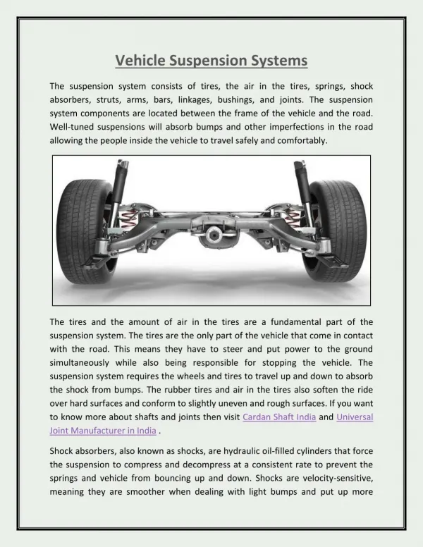
The fatigue is mostly the common cause of failure in most structural elements subjected to repeated and cyclic loads. This is mostly localized and takes place in elements of constant cyclic load application. This project deals with the fatigue in leaf spring carried out in spring steel 55SiMn90 to find the premature failure in the leaf spring due to variation in application of load. The spring is subjected to both tensile and compressive stress by means of fatigue testing machine. The leaf spring is obtained from the light commercial vehicle and it is subjected to varying stress until the failure occurs in the material. The results are obtained from the test specimen is evaluated to find its tensile and compressive strain. These values obtained will be helpful in analyzing the failure of the material subjected to reversed stress. It is also used for assistance to arrest the failure by implementing measures to culminate the effect of failure to certain extent. B. M. Swami Punniakodi | N. Karthik "Fatigue Life Prediction of Leaf Spring used in the Suspension System of Light Commercial Vehicle" Published in International Journal of Trend in Scientific Research and Development (ijtsrd), ISSN: 2456-6470, Volume-3 | Issue-2 , February 2019, URL: https://www.ijtsrd.com/papers/ijtsrd21573.pdf Paper URL: https://www.ijtsrd.com/engineering/mechanical-engineering/21573/fatigue-life-prediction-of-leaf-spring-used-in-the-suspension-system-of-light-commercial-vehicle/b-m-swami-punniakodi<br>

E N D
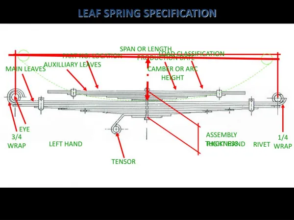
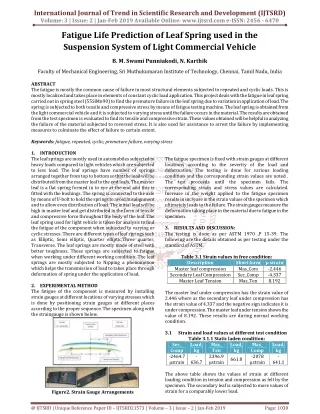
International Journal of Trend in Scientific Research and Development (IJTSRD) Volume: 3 | Issue: 2 | Jan-Feb 2019 Available Online: www.ijtsrd.com e-ISSN: 2456 - 6470 Fatigue Life Prediction of Leaf Spring used in the Suspension System of Light Commercial Vehicle B. M. Swami Punniakodi, N. Karthik Faculty of Mechanical Engineering, Sri Muthukumaran Institute of Technology, Chennai, Tamil Nadu, India ABSTRACT The fatigue is mostly the common cause of failure in most structural elements subjected to repeated and cyclic loads. This is mostly localized and takes place in elements of constant cyclic load application. This project deals with the fatigue in leaf spring carried out in spring steel (55SiMn90) to find the premature failure in the leaf spring due to variation in application of load. The spring is subjected to both tensile and compressive stress by means of fatigue testing machine. The leaf spring is obtained from the light commercial vehicle and it is subjected to varying stress until the failure occurs in the material. The results are obtained from the test specimen is evaluated to find its tensile and compressive strain. These values obtained will be helpful in analyzing the failure of the material subjected to reversed stress. It is also used for assistance to arrest the failure by implementing measures to culminate the effect of failure to certain extent. Keywords: fatigue, repeated, cyclic, premature failure, varying stress 1.INTRODUCTION Theleaf springs are mostly used in automobiles subjected to heavy loads compared to light vehicles which are subjected to less load. The leaf springs have number of springs arranged together from top to bottom so that the load will be distributed from the master leaf to the end leafs. The master leaf is a flat spring formed in to eye at the end and this is fitted with the bushings. The spring is connected to the axle by means of U-bolt to hold the springs to avoid misalignment and to allow even distribution of load. The initial load will be high in master leaf and get distributed in the form of tensile and compressive force throughout the body of the leaf. The leaf spring used for light vehicle is taken for analysis to find the fatigue of the component when subjected to varying or cyclic stresses. There are different types of leaf springs such as Elliptic, Semi elliptic, Quarter elliptic,Three quarter, Transverse. The leaf springs are mostly made of steel with better toughness. These springs are subjected to fatigue when working under different working condition. The leaf springs are mostly subjected to Nipping a phenomenon which helps the transmission of load to takes place through deformation of spring under the application of load. 2.EXPERIMENTAL METHOD The fatigue of the component is measured by installing strain gauges at different locations of varying stresses which is done by positioning strain gauges at different places according to the proper sequence. The specimen along with the straingauge is shown below. The fatigue specimen is fixed with strain gauges at different locations according to the severity of the load and deformation. The testing is done for various loading condition and the corresponding strain values are noted . The test proceeds until the specimen fails. The corresponding strain and stress values are calculated. Increase in the weight applied to the fatigue specimen results in increase in the strain values of the specimen which ultimately leads to the failure. The strain gauges measure the deformation taking place in the material due to fatigue in the specimen. 3.RESULTS AND DISCUSSION: The testing is done as per ASTM 1970 ,P 15-39. The following are the details obtained as per testing under the standard of ASTM. Table 3.1 Strain values in free condition: Description Master leaf compression Secondary Leaf Compression Master Leaf Tension The master leaf under compression has the strain value of 2.446 where as the secondary leaf under compression has the strain value of 4.337 and the negative sign indicates it is under compression. The master leaf under tension shows the value of 8.192. These results are during normal working condition. 3.1 Strain and load values at different test condition Table 3.1.1 Static laden condition: Sec_ Comp kg Ten -2464.7 µstrain 636.7 µstrain The above table shows the values of strain at different loading condition in tension and compression as felt by the specimen. The secondary leaf is subjected to more values of strain for a comparably lower load. Short form µ strain Mas_Com Sec_Comp Mas_Ten -2.446 -4.337 8.192 Load, Mas_ Load, kg Mas_ Comp -2078 µstrain Load, kg - 641.1 - 2396.9 661.8 Figure2. Strain Gauge Arrangements @ IJTSRD | Unique Reference Paper ID – IJTSRD21573 | Volume – 3 | Issue – 2 | Jan-Feb 2019 Page: 1030
International Journal of Trend in Scientific Research and Development (IJTSRD) @ www.ijtsrd.com eISSN: 2456-6470 Table 3.1.2 Articulation: Front RH on ramp Mas_Ten 4561µstrain 1294.629 -900µstrain -310.295 Sec_Comp -4582µstrain Load, kg -155.68 Load, kg Mas_Comp Load, Kg The above table shows the variation of strains in the secondary as well as master leaf during tension and compression on the right hand side of the vehicle on the ramp. It is seen that the secondary leaf is subjected compression with high values of strain when compared with master leaf in compression. The master leaf has a high tension strain value when compared with the compression value. Table 3.1.3 Articulation Front LHon ramp Sec_comp Load, kg Mas_Ten -907.5 strain -255.071 944 µstrain 237.0263 -388 µstrain The above table indicates the value of tension and compression when strained and it is found that secondary leaf compression is larger than the master leaf compression and this will also be used for the calculation of fatigue at different stages of loading. Table 3.1.4 Rough load: Sec_Comp Load, Kg Mas_Ten Max Val. -4708.3 µStrain -1186.64 Min Val. -378.4 µStrain 479.73 µStrain Mean -2866.7 µStrain 2833.9 µStrain The above values shows the maximum and minimum, compression and tension values when the specimen is subjected to rough load. It shows the minimum value of strain in compression for a load of 1186.4 kgs as -378.4 and the master leaf is subjected to tensile strain of 479.73 and compressive strain of 314.67 for a load of 1221.98 kgs. The magnitude of compressive strain is higher in secondary leaf than the compressive and tensile strain in master leaf and it is a major problem in automobile. Table 3.1.5 Paved Road: Sec_Comp Load, Kg Mas_Ten Max Val-3827.2 µStrain -970.6 Min Val -2358.1 µStrain 2345.1 µStrain Mean -3006 µStrain 2955.3 µStrain The value of compressive and tensile strain under paved road is given above and the value of strain in secondary leaf under compression is 3827.2 for a load of 970.6 kgs and the corresponding values for the applied load is given above. Table 3.1.6 Braking (60 KMPH to 0) (normal braking): Sec_Comp Load, kg Mas_Ten Max Val -4062.1 µStrain -1028.3 Min Val -2500.8 µStrain 2491.5 µStrain Mean -3309.4 µStrain 3229 µStrain The above table indicates the value of compressive and tensile strain during normal braking condition and it is found that secondary leaf has a maximum value of compressive strain of 4062.1 compared to 3456.3 in master leaf for a lower load in secondary leaf. Table 3.1.7 Kerb hitting: RH wheel on bump Sec_Comp Load, kg Mas_Ten Max Val -4129.1 µStrain -1044.68 Min Val -2104.5 µStrain 2121.6 µStrain Mean -3051.6 µStrain 2997.4 µStrain RH wheel on bump Sec_Comp Load, kg Mas_Ten Max Val -4112.3 µStrain -1040.56 Min Val -1700.8 µStrain 1747.2µStrain Mean -3085.5 µStrain 3026.7µStrain The above details illustrates the behavior of leaf spring subjected to kerb hitting. It shows there is a marginal increase in the value of strain with the value of load as it varies from 1040.56 kgs to 1044.68 kgs.This variation in strain will largely influence the life of the spring.In all the cases the secondary spring is subjected to large value of strain which is the basic factor for failure. Load, kg Mas_Comp Load, Kg Mas_Comp -4145.6 µStrain 314.67 µStrain -2803.7 µStrain Load, Kg 4685.9 µstrain 1331.19 -1221.98 Load, Kg Mas_Comp -3491.2 µStrain -1373.3 µStrain -2634.2 µStrain Load, Kg 3727.1 µStrain 1050.9 -1038.16 Load, kg Mas_Comp -3456.3 µStrain -2442.4 µStrain -2952.5 µStrain Load, kg 3992.5 µStrain 1128.401 -1028.36 Load,kg Mas_Comp -3787.5 µStrain -1948 µStrain -2919.8 µStrain Load,kg 4057.1 µStrain 1147.289 -1221.39 Load, kg Mas_Comp -4065.3µStrain -1359.7µStrain -2957µStrain Load, kg 4056µStrain 1146.968 -1196.9 @ IJTSRD | Unique Reference Paper ID – IJTSRD21573 | Volume – 3 | Issue – 2 | Jan-Feb 2019 Page: 1031
International Journal of Trend in Scientific Research and Development (IJTSRD) @ www.ijtsrd.com eISSN: 2456-6470 4.CONCLUSION The above results after careful monitoring shows that maximum value of tensile strain as 4685 μ strain in master leaf and this induces a maximum compressive strain on the secondary leaf on the rough road condition. The stress value is 93.7 kg/mm2. The compressive stress of 80 kg/mm2 is induced on the specimenThe magnitude of this tensile stress is higher than the compressive stress induced by shot peening and the vehicle operates mostly on tensile stress on the leaf which induces compressive stress . This may be reason for spring failure. Thus the cause for fatigue failure in leaf springs was calculated on the basis of tensile and compressive strain occurred due to variation in load . ACKNOWLEDGMENT We show our sincere thanks to Mr. GIRIDHAR RAJU, Human Resource Manager, and Mr. K. PRAKASH, HR Sengadu Plant, Mr. S. MANIVANNAN, Manager in component testing, Mr. K. SARAVANAN, Assistant manager in vehicle testing at Nissan Ashok Leyland Technologies (NALT) for allowing and helping us with their valuable guidance, suggestions and constant encouragement which paved way for the successful completion of the project work at Nissan Ashok Leyland Technologies Limited at Sengadu. References [1]S. Manson: A complex subject – some simple approximations. Experimental Mechanics 5, Nr. 7, 1965. [2]U Muralidharan, S. S. Manson: A Modified Universal Slopes Equation fro Characteristics of Metals. Journal of Engineering Materials and Technology 110, 1988. Estimation of Fatigue [3]A. Bäumel Jr., T. Seeger: Materials Data for Cyclic Loading, Supplement 1. Materials Science Monographs 61, Elsevier, 1990 [4]Hoffmann, K. P.1989. An Introduction to Measurements Using Strain Gages. Darmstad: Hottier Baldwin Messtechinik GmbH. Airila, M. Ekman, K. Hautala, P. Kivioja, S. Kleimola, M. Martikka, H. Miettinen, J. Niemi, E. Ranta, A. Rinkinen, J. Salonen, P. Verho, A. Vilenius, M. & Välimaa, V P.1997, Koneenosien suunnittelu. Helsinki: Werner Söderström Osakeyhtiö. [5]Vishay Micro-Measurement. The three-wire quarter bridge circuit, Application note TT-612, 2005 Read 8.4.2011. @ IJTSRD | Unique Reference Paper ID – IJTSRD21573 | Volume – 3 | Issue – 2 | Jan-Feb 2019 Page: 1032