Download
1 / 5
50 likes | 76 Vues
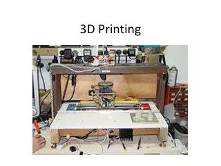
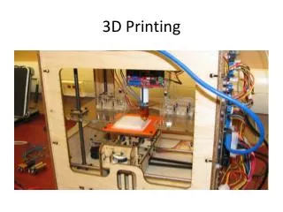
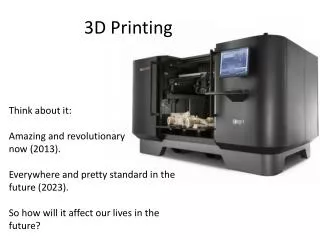
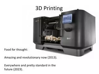
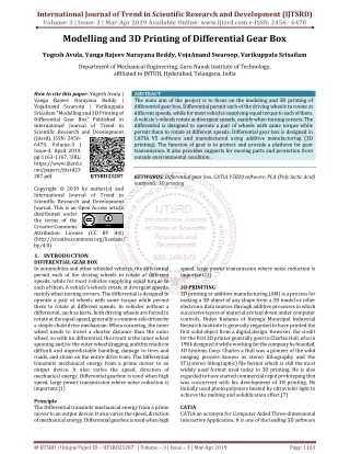
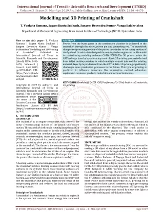
Power from the burnt gases in the combustion chamber is delivered to the crankshaft through the piston, piston pin and connecting rod. The crankshaft changes reciprocating motion of the piston in cylinder to the rotary motion of the flywheel. Crankshaft is designed for multi cylinder engine and its 3D model is created using modeling software CATIA V5R20.The 3D printer prints the CATIA design layer by layer forming a real object. 3D printing process is derived from inkjet desktop printers in which multiple deposit jets and the printing material, layer by layer derived from the CATIA data. 3D printing significantly challenges mass production processes in the future. This type of printing is predicted to influence industries, like automotive, medical, education, equipment, consumer products industries and various businesses. T. Venkata Ramana | Sagam Kunta Subhash | Sangem Devendra Kumar | Vanga Balakrishna "Modelling and 3D Printing of Crankshaft" Published in International Journal of Trend in Scientific Research and Development (ijtsrd), ISSN: 2456-6470, Volume-3 | Issue-3 , April 2019, URL: https://www.ijtsrd.com/papers/ijtsrd23224.pdf Paper URL: https://www.ijtsrd.com/engineering/mechanical-engineering/23224/modelling-and-3d-printing-of-crankshaft/t-venkata-ramana<br>

E N D
International Journal of Trend in Scientific Research and Development (IJTSRD) Volume: 3 | Issue: 3 | Mar-Apr 2019 Available Online: www.ijtsrd.com e-ISSN: 2456 - 6470 Modelling and 3D Printing of Crankshaft T. Venkata Ramana, Sagam Kunta Subhash, Sangem Devendra Kumar, Vanga Balakrishna Department of Mechanical Engineering, Guru Nanak Institute of Technology, JNTUH, Hyderabad, India How to cite this paper: T. Venkata Ramana | Sagam Kunta Subhash | Sangem Devendra Kumar | Vanga Balakrishna "Modelling and 3D Printing of Crankshaft" Published in International Journal of Trend in Scientific Research and Development (ijtsrd), ISSN: 2456- 6470, Volume-3 | Issue-3 , April 2019, pp.1039-1043, URL: https://www.ijtsrd.c om/papers/ijtsrd23 224.pdf Copyright © 2019 by author(s) and International Journal of Trend in Scientific Research and Development Journal. This is an Open Access article distributed under the terms of the Creative Commons Attribution License (CC BY 4.0) (http://creativecommons.org/licenses/ by/4.0) 1.INTRODUCTION CRANKSHAFT The crankshaft is an engine component that converts the linear (reciprocating) motion of the piston into rotary motion. The crankshaft is the main rotating component of an engine and is commonly made of ductile iron. Features of a crankshaft include the crankpin journal, throw, bearing journals, counterweights, crank gear, and a power take-off (PTO). A crankpin journal is a precision ground surface that provides a rotating pivot point to attach the connecting rod to the crankshaft. The throw is the measurement from the center of the crankshaft to the center of the crankpin journal, which is used to determine the stroke of an engine. The throw is equal to one-half the stroke. The longer the throw, the greater the stroke, or distance, a piston travels.[1] A bearing journal is a precision ground surface within which the crankshaft rotates. Bearing journals mate with bearing surfaces in the cylinder block. Most bearing surfaces are machined integrally in the cylinder block. Some engines feature a low-friction bushing or a ball or tapered roller bearing. A counterweight is a protruding mass integrally cast into the crankshaft that partially balances the forces of the reciprocating piston and reduces the load on crankshaft bearing journals. Principle of Crankshaft A crankshaft is a fundamental feature in a vehicle’s engine. It is the system that converts linear energy into rotational ABSTRACT Power from the burnt gases in the combustion chamber is delivered to the crankshaft through the piston, piston pin and connecting rod. The crankshaft changes reciprocating motion of the piston in cylinder to the rotary motion of the flywheel. Crankshaft is designed for multi cylinder engine and its 3D-model is created using modeling software CATIA V5R20.The 3D printer prints the CATIA design layer by layer forming a real object. 3D printing process is derived from inkjet desktop printers in which multiple deposit jets and the printing material, layer by layer derived from the CATIA data. 3D printing significantly challenges mass production processes in the future. This type of printing is predicted to influence industries, like automotive, medical, education, equipment, consumer products industries and various businesses. KEYWORDS: Crankshaft, CATIA V5R20 software; PLA (Poly lactic Acid) materials; 3D printing IJTSRD23224 energy. This enables the wheels to drive the car forward. All the pistons in the engine are attached to the crank which is also connected to the flywheel. The crank works in association with other engine components to achieve a synchronized motion. This process, which enables the vehicle’s engine to run.[3] 3D PRINITING 3D printing or additive manufacturing (AM) is a process for making a 3D object of any shape from a 3D model or other electronic data sources through additive processes in which successive layers of material are laid down under computer controls. Hideo Kodama of Nayoga Municipal Industrial Research Institute is generally regarded to have printed the first solid object from a digital design. However, the credit for the first 3D printer generally goes to Charles Hull, who in 1984 designed it while working for the company he founded,3D Systems Corp. Charles a Hull was a pioneer of the solid imaging process known as stereo lithography and the STL(stereo lithographic) file format which is still the most widely used format used today in 3D printing. He is also regarded to have started commercial rapid prototyping that was concurrent with his development of 3D printing. He initially used photo polymers heated by ultraviolet light to achieve the melting and solidification effect. @ IJTSRD | Unique Paper ID – IJTSRD23224 | Volume – 3 | Issue – 3 | Mar-Apr 2019 Page: 1039
International Journal of Trend in Scientific Research and Development (IJTSRD) @ www.ijtsrd.com eISSN: 2456-6470 CATIA CATIA an acronym for Computer Aided Three-dimensional Interactive Application. It is one of the leading 3D software used by organizations in multiple industries ranging from aerospace, automobile to consumer products. CATIA is a multiplatform 3D software suite developed by Dassault Systems, encompassing CAD, CAM as well as CAE. Dassault is a French engineering giant active in the field of aviation, 3D design, 3D digital mock-ups, and product lifecycle management (PLM) software. CATIA is a solid modelling tool that unites the 3D parametric features with 2D tools and also addresses every design-to-manufacturing process. In addition to creating solid models and assemblies, CATIA also provides generating orthographic, section, auxiliary, isometric or detailed 2D drawing views. It is also possible to generate model dimensions and create reference dimensions in the drawing views. The bi-directionally associative property of CATIA ensures that the modifications made in the model are reflected in the drawing views and vice-versa. The first release of CATIA was way back in 1977, and the software suite is still going strong more than 30 years later. While CATIA V6 is just being released, the most popular version of CATIA is V5 which was introduced in 1998. That said, it is important to note that each version of CATIA introduces considerable additional functionality. For example, V4 (introduced in 1192) offered enhancements to the Assembly Modeling Product including easy-to-use graphical tree-based assembly management. V5 and V6 saw changes in the way data is handled. Dassault Systems typically offers new updates, releases and bug fixes for each version. 2.LITERATURE REVIEW The idea of printing 3D objects conceptualized and was patented by Chuck Hull of 3D Systems Inc. in 1986. Sachs et al. at MIT obtained a patent for making a component by depositing a first layer of a fluent porous material, such as a powder, in a confined region and then depositing a binder material to selected regions of the layer of powder material to produce a layer of bonded powder material at the selected regions. Such steps are repeated a selected number of times to produce successive layers of selected regions of bonded powder material so as to form the desired component. The un-bonded powder material is then removed. In some cases the component may be further processed, for example, by heating it to further strengthen the bonding thereof. MIT's DPTM process laboratory lead the way in 3D printing process research in the area of gradient index lenses, tooling for low cast casting, fine ceramic components for electronic application, tungsten carbide cutting tools, and metal matrix composites. D.A. Roberson et al. evaluated the capability of five desktop additive manufacturing (AM) machines based on the ability to produce a standard component. This work also developed a model/method for evaluating and ranking AM technologies based on select criteria that can facilitate purchasing decisions. A standard part was designed and printed on each machine, and evaluated based on dimensional accuracy and surface finish. Additionally, the machines were compared based on build time for single and multiple parts as well as material consumption and unit cost. The ranking system presented in this paper has demonstrated the ability to discriminate between different AM processes and rank these systems based on quantitative measures. Lee and Kim analyzed the trend of 3D printing-related patents for the last 10 years to investigate patent application trends by country, by year, by assignee and by technology. Furthermore, the paper analyzed the patent trend on 3D printers and materials used to secure original technologies and a portfolio of application technologies in medium and long terms. 11 Utela et al. presented a paper organizing the process of 3DP implementation into five steps (powder formulation, binder method selection, binder formulation and testing, printing process specification, and post-processing specification) and presented a review of the literature relevant to each step in 3DP implementation. Huang et al. reviewed the societal impact of additive manufacturing in 1.customized healthcare products to improve population health and quality of life, 2.reduced environmental impact for manufacturing sustainability, and 3.simplified supply chain to increase efficiency and responsiveness in demand fulfillment. Their review also identified the need for further research in the areas of life-cycle energy consumption evaluation and potential occupation hazard assessment manufacturing. Berman in his paper examined the characteristics and applications of 3D printing for mass customization. He argued that there are a number of promising applications exist in the production of replacement parts, dental crowns, and artificial limbs, as well as in bridge manufacturing. 3D printing market allow firms to profitably serve small market segments, and enable companies to operate with little or no inventory and significantly reduce the need for factory workers. Thompson et al. provided an overview of the major advancements, challenges and physical attributes related to Direct Laser Deposition (DLD) process. The Part I focused on the thermal/fluidic phenomena during the powder-fed DLD process, which directly influence the solidification heat transfer, which thus affects the part’s microstructure and associated thermo-mechanical properties. In Part II Shamsaei et al. focused on the mechanical properties, characteristics, behavior and microstructure of parts manufactured via DLD and post DLD process parameters (e.g. heat treatment, machining). controlling/optimizing the DLD process for targeted part design discussed – with an emphasis on monitored part temperature and/or melt pool morphology. Singh et al. reviewed the recent technological advancements in materials and in technological aspects of 3D printing, identified future challenges and potential applications in engineering, manufacturing and tissue engineering. Also provided number of patents filed in materials, their applications and industry-wise patent filing trends. 12 The overall 3D printing technology publishing trend is provided in Figure 7. The exponential rise in the number of publications clearly demonstrates that 3D printing for additive Methods for @ IJTSRD | Unique Paper ID - IJTSRD23224 | Volume – 3 | Issue – 3 | Mar-Apr 2019 Page: 1040
International Journal of Trend in Scientific Research and Development (IJTSRD) @ www.ijtsrd.com eISSN: 2456-6470 technology is going to dominate the additive manufacturing filed in the coming years. The overall 3D printing patent publication trend is provided in Figure 08. The exponential rise in the patent applications clearly demonstrates that 3D printing technology is going to dominate additive manufacturing in the coming years. The following sections will focus on the material, printing technology, 3D printing equipment and part quality issues and standards.[5] 3.METHODOLOGY GENERAL PRINCIPLES Modeling 3D printable models can be created with the help of CATIA design packages or via 3D scanner. The manual modeling process of preparing geometric data for 3D computer graphics is similar to method sculpting. 3D modeling is a process of analyzing and collecting data on the shape and appearance of an object. Based on this data, 3D models of the scanned object can be produced. Both manual and automatic creations of 3Dprinted models are very difficult for average consumers. That is why several market-places have emerged over the last years among the world. The most popular are Shape ways, Thing verse, My Mini Factory, and Threading. Printing Before printing a 3D model from .STL file, it must be processed by a piece of software called a "slicer" which converts the 3D model into a series of thin layers and produces a G-code file from .STL file containing instructions to a printer. There are several open source slicer programs exist, including, Slic3r, KISSlicer, and Cura. The 3D printer follows the G-code instructions to put down successive layers of liquid, powder, or sheet material to build a model from a series of cross-sections of a model. These layers, which correspond to the virtual cross sections from the CAD model ,are joined or fused to create the final shape of a model. The main advantage of this technique is its ability to create almost any shape or geometric model. Construction of a model with existing methods can take anywhere from several hours today’s, depending on the method used and the size and complexity of the model. Additive systems can typically reduce this time to very few hours; it varies widely depending on the type of machine used and the size and number of models being produced. 29 Finishing Although the printer-produced resolution is sufficient for many applications, printing a slightly oversized version of the object in standard resolution and then removing material with a higher-resolution process can achieve greater precision. As with the AccurateiD-20 and other machines Press Release. International Manufacturing Technology shows some additive manufacturing techniques are capable of using multiple materials in the course of constructing parts. 4.3D PRINTING TECHNIQUE FUSED DEPOSITION MODELING Fused deposition modeling (FDM) method was developed by S. Scott Crump in the late 1980s and was designed in 1990 by Stratasys. After the patent on this technology expired, a large open source development community developed and commercial variants utilizing this type of 3D printer appeared. As a result, the price of FDM technology has dropped by two orders of magnitude since its creation. In this technique, the model is produced by extruding small beads of material which harden to form layers. A thermoplastic filament or wire that is wound into a coil is unwinding to supply material to an extrusion nozzle head. The nozzle head heats the material up to the certain temperature and turns the flow on and off. Typically the stepper motors are employed to move the extrusion head in the z-direction and adjust the flow according to the requirements. The head can be moved in both horizontal and vertical directions, and control of the mechanism is done by a computer-aided manufacturing (CAM) software package running on a microcontroller. Figure 1.Fused deposition method MATERIALS USED .Poly Lactic Acid [PLA] Poly lactic acid (PLA) (is derived from corn and is biodegradable) is another well-spread material among 3Dprinting enthusiasts. It is a biodegradable thermoplastic that is derived from renewable resources. As a result PLA materials are more environmentally friendly among other plastic materials. The other great feature of PLA is its biocompatibility with a human body. The structure of PLA is harder than the one of ABS and material melts at 180 –220°C which is lower than ABS. PLA glass transition temperature is between 60 – 65 ° C, so PLA together with ABS could be some good options for any of your projects. Technical Specifications Density - 1.3 g/cm³ (81 lb/ft³) Elastic (Young's, Tensile) Modulus - 2.0 to 2.6 GPa (0.29 to 0.38 x 10³ psi) Elongation at Break - 6.0 % Flexural Modulus - 4.0 GPa (0.58 x 10⁶ psi) Flexural Strength - 80 MPa (12 x 10³ psi) Glass Transition Temperature - 60 °C (140 °F) Heat Deflection Temperature At 455 kPa (66 psi) - 65 °C (150 °F) Melting Onset (Solidus) - 160 °C (320 °F) Shear Modulus- 2.4 GPa (0.35 x 10⁶ psi) Specific Heat Capacity - 1800 J/kg-K Strength to Weight Ratio - 38 kN-m/kg Tensile Strength : Ultimate (UTS) - 50 MPa (7.3 x 10³ psi) Thermal Conductivity - 0.13 W/m-K Thermal Diffusivity - 0.056 @ IJTSRD | Unique Paper ID - IJTSRD23224 | Volume – 3 | Issue – 3 | Mar-Apr 2019 Page: 1041
International Journal of Trend in Scientific Research and Development (IJTSRD) @ www.ijtsrd.com eISSN: 2456-6470 Material Properties of Poly Lactic Acid [PLA] Temperature - 180°C Flow Tweak - 0.95 Bed Temperature - 60°C Bed Preparation - apply glue stick 2 layer 5.EXPERIMENTATION MODELLING OF CRANKSHAFT To add your model, click on the plus icon in the middle. Choose your file and it will be loaded onto the screen. Use the “Pan”, “Move” and “Rotate” tools to look around. You can also use the shortcuts. One thing you might notice is an orange warning sign. This means your models are “Invalid” and that they need to be repaired. If you unselect them, they will be colored red. Repairing is a very smooth and efficient process in Idea Maker. Here’s how to do it: 1.Select the model. 2.Click “Repair” on the toolbar Transforming Your Model With IdeaMaker, it’s also possible to transform your model. The tools are basic but often enough to get the job done. You can move, rotate and scale your model using the tools in the toolbar. Here’s how to transform your object: 1.Select your model, and then choose the tool you want. 2.3D axes will appear on your model — lines for “Move” and “Scale” or circles for “Rotate”. Click and drag the lines to transform your model. 3.Alternatively, you can insert manual values for the transformations in the window that pops open on the left. 4.If you want to print the model as big as your printer allows, you can use the “Max Fit” tool. This scales the model to precisely fit your printer. Setting up the Print Settings PROCEDURE FOR SLICING AND 3D PRINTING Adding and Repairing Your Model The settings are abundant and you can adjust almost anything you can think of in IdeaMaker’s settings tab. From “Coasting Distance” to “Infill Acceleration”, there are settings present in IdeaMaker that usually aren’t present in other 3D Slicers. Once you’re done adjusting the settings, click “Okay” and then “Save and Close”. @ IJTSRD | Unique Paper ID - IJTSRD23224 | Volume – 3 | Issue – 3 | Mar-Apr 2019 Page: 1042
International Journal of Trend in Scientific Research and Development (IJTSRD) @ www.ijtsrd.com eISSN: 2456-6470 Slicing and Printing 6.RESULTS AND DISCUSSION Crankshaft is designed and 3D printed by using fused deposition modeling. After setting up the print settings, it’s time to finally slice it into g-code: 1.Click on the play icon labeled “Start Slicing” or use Ctrl+P. It might take some time to slice the model. 2.Once the slicing is finished, you’ll see a window indicating the estimated price, print duration, etc. 3.If you’ve connected your printer, you can print directly from Idea Maker by clicking “Export”. However, if you don’t have your printer connected, it will export the g- code file. 4.Selecting “Upload” will upload the g-code to the printer wirelessly. This is the case for Raise3D printers. 5.If you want to preview your g-code, click on “Preview”. The preview screen itself will take some time to load. Temperature maintains Right Nozzle 240oC Left Nozzle 0oC Heat Bed 109oC 3D printing the crankshaft by FDM 7.CONCLUSION In this journal modelling of a CRANKSHAFT is carried out with the of CATIA v5 Software by using of machine design. After creating model we save the component in stl. file. Import the component into the 3D Printing machine. And then we apply the G-CODES to the component. And then we get the component 8.REFERENCE [1]http://courses.washington.edu/engr100/Section_Wei/ engine/UofWindsorManual/Crankshaft.htm [2]https://en.wikipedia.org/wiki/Crankshaft [3]http://www.ijpres.com/pdf33/37.pdf [4]http://what-when-how.com/crankshaft/crankshaft- nomenclature/ [5]https://pdfs.semanticscholar.org/e143/888b62e0720f e5560d131f462e0cd7737756.pdf [6]https://www.stratasysdirect.com/manufacturing- services/3d-printing [7]https://www.designtechcadacademy.com/knowledge- base/catia-training [8]https://grabcad.com/tutorials/catia-v5-basic-tutorial-- 1 [9]https://www.ijert.org/research/a-review-paper-on- 3d-printing-aspects-and-various-processes-used-in- the-3d-printing-IJERTV6IS060409.pdf [10]http://ijarece.org/wp- content/uploads/2016/07/IJARECE-VOL-5-ISSUE-7- 2001-2004.pdf @ IJTSRD | Unique Paper ID - IJTSRD23224 | Volume – 3 | Issue – 3 | Mar-Apr 2019 Page: 1043