Download
1 / 7
90 likes | 179 Vues
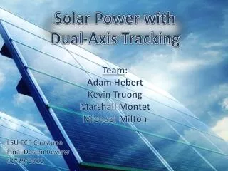
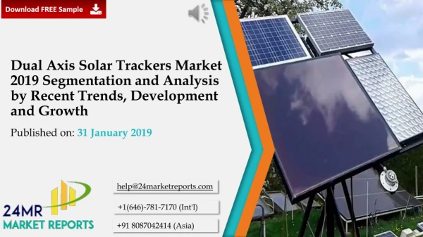
Solar energy is rapidly advancing as an important means of renewable energy resource. Many of the solar panels throughout the world are positioned with the fixed angles. Solar tracking enables more solar energy to be generated because the solar panel is able to maintain a perpendicular profile to the sun's rays. Solar trackers move the solar panel to follow the sun trajectories and keep the orientation of the solar collector at an optimal tilt angle. The main objective of this research is to develop an dual axis solar tracking system azimuth angle as well as altitude angle in which solar panel will keep aligned with sunlight in order to maximize in harvesting solar power generation from the solar panel and to show for the output power with dual axis solar tracking system is higher than without tracking system in the sunny day condition. This research focus on the development of new approach to control the dual axis solar tracking system by using DC motor and controller design is simple structure and saving cost by using LM 324 op amp IC. Design and construction of a prototype for solar tracking system which detects the sunlight using Light Dependent Resistors LDR and DC motor is used to control the appropriate position of the panel where it can receive maximum sunlight. In this dual axis control system, lock anti phase drive method is used for H bridge. From the hardware testing, the solar tracker is proven more effective for capturing the maximum sunlight source for solar harvesting applications. Swe Swe Mar | Zarchi San | Thuzar Mon "Analysis of Dual-axis Solar Tracking System by using Lock Anti-Phase Drive Method" Published in International Journal of Trend in Scientific Research and Development (ijtsrd), ISSN: 2456-6470, Volume-2 | Issue-6 , October 2018, URL: https://www.ijtsrd.com/papers/ijtsrd18594.pdf Paper URL: http://www.ijtsrd.com/engineering/electrical-engineering/18594/analysis-of-dual-axis-solar-tracking-system-by-using-lock-anti-phase-drive-method/swe-swe-mar<br>

E N D
International Journal of Trend in International Open Access Journal International Open Access Journal | www.ijtsrd.com International Journal of Trend in Scientific Research and Development (IJTSRD) Research and Development (IJTSRD) www.ijtsrd.com ISSN No: 2456 ISSN No: 2456 - 6470 | Volume - 2 | Issue – 6 | Sep 6 | Sep – Oct 2018 Analysis of Dual-axis xis Solar Tracking System by u using Lock Anti Anti-Phase Drive Method Swe Swe Mar1, Zarchi San2, Thuzar Mon3 ME Candidate, 2Lecturer,3Assistant Lecturer EP Department, Pyay Technological University, Pyay,Myanmar Swe Swe Mar 1ME Candidate EP Department, Pyay Technological Myanmar I. The increasing demand of energy, the depletion of fossil fuel reserves, the unexpected events taking place on the international scene (local armed conflicts, natural disasters like earthquakes, floods, hurricanes, etc.) that have the potential to partially cripple the energetic systems, proves that the energy s diversity is a serious aspect that the mankind should seriously consider when deciding the short and middle term energy policy. The general opinion shared by the most part of the specialists supports the idea that the exclusive dependence on the energy produced from fossil fuels (coal, oil, nuclear, etc.) is hazardous, unsustainable and harmful for the environment. In this context, many developed countries (e.g. USA, Germany, Spain, Denmark, France, Italy etc.) launched in the last decades ambit supporting the rapid development of alternative energetic technologies based on: solar energy, wind energy, tidal and wave energy, biomass etc. One of the most promising renewable energy sources characterized by a huge potential of conve electrical power is the solar energy. The conversion of solar radiation into electrical energy by Photo (PV) effect is a very promising technology, being clean, silent and reliable, with very small maintenance costs and small ecological impact. Solar tracking is obvious way to improve the efficiency of solar power plants. The sun’s position in the sky varies both with the seasons and times of day as the sun moves across the sky. All concentrated solar systems have trackers because the sy not produce energy unless directed correctly toward the sun. ABSTRACT Solar energy is rapidly advancing as an important means of renewable energy resource. Many of the solar panels throughout the world are positioned with the fixed angles. Solar tracking enables more solar energy to be generated because the solar panel is able to maintain a perpendicular profile to the sun’s rays. Solar trackers move the solar panel to follow the sun trajectories and keep the orientation of the solar collector at an optimal tilt angle. The main objective of this research is to develop an dual tracking system (azimuth angle as well as altitude angle) in which solar panel will keep aligned with sunlight in order to maximize in harvesting solar power generation from the solar panel and to show for the output power with dual-axis solar tracking system is higher than without tracking system in the sunny day condition. This research development of new approach to control the dual solar tracking system by using DC motor and controller design is simple structure and saving cost by using LM 324(op-amp) IC. Design and construction of a prototype for solar tracking system which detects the sunlight using Light Dependent Resistors (LDR) and DC motor is used t appropriate position of the panel where it can receive maximum sunlight. In this dual-axis control system, lock anti-phase drive method is used for H From the hardware testing, the solar tracker is proven more effective for capturing the maximum sunlight source for solar harvesting applications. Keywords:Light Dependent Resistor, Solar Tracker, Dual-axis Control System, Lock Anti Method, Solar Panel. INTRODUCTION The increasing demand of energy, the depletion of fuel reserves, the unexpected events taking place on the international scene (local armed conflicts, natural disasters like earthquakes, floods, hurricanes, etc.) that have the potential to partially cripple the energetic systems, proves that the energy security and diversity is a serious aspect that the mankind should seriously consider when deciding the short and middle term energy policy. The general opinion shared by the most part of the specialists supports the idea that the Solar energy is rapidly advancing as an important means of renewable energy resource. Many of the solar panels throughout the world are positioned with enables more solar energy to be generated because the solar panel is able to maintain a perpendicular profile to the sun’s rays. Solar trackers move the solar panel to follow the sun trajectories and keep the orientation of the solar l tilt angle. The main objective of this research is to develop an dual-axis solar tracking system (azimuth angle as well as altitude angle) in which solar panel will keep aligned with sunlight in order to maximize in harvesting solar the solar panel and to show for e energy produced from fossil fuels (coal, oil, nuclear, etc.) is hazardous, unsustainable and harmful for the environment. In this context, many developed countries (e.g. USA, Germany, Spain, Denmark, France, Italy etc.) launched in the last decades ambitious programs for supporting the rapid development of alternative energetic technologies based on: solar energy, wind energy, tidal and wave energy, biomass etc. axis solar tracking system is higher than without tracking system in the sunny day condition. This research development of new approach to control the dual-axis by using DC motor and controller design is simple structure and saving cost focus focus on on the the amp) IC. Design and One of the most promising renewable energy sources characterized by a huge potential of conversion into electrical power is the solar energy. The conversion of solar radiation into electrical energy by Photo-Voltaic (PV) effect is a very promising technology, being clean, silent and reliable, with very small maintenance impact. construction of a prototype for solar tracking system which detects the sunlight using Light Dependent Resistors (LDR) and DC motor is used to control the appropriate position of the panel where it can receive axis control system, phase drive method is used for H-bridge. From the hardware testing, the solar tracker is proven the maximum sunlight Solar tracking is obvious way to improve the efficiency of solar power plants. The sun’s position in the sky varies both with the seasons and times of day as the sun moves across the sky. All concentrated solar systems have trackers because the systems do not produce energy unless directed correctly toward Light Dependent Resistor, Solar Tracker, axis Control System, Lock Anti-Phase Drive @ IJTSRD | Available Online @ www.ijtsrd.com www.ijtsrd.com | Volume – 2 | Issue – 6 | Sep-Oct 2018 Oct 2018 Page: 653
International Journal of Trend in Scientific Research and Development (IJTSRD) ISSN: 2456 International Journal of Trend in Scientific Research and Development (IJTSRD) ISSN: 2456 International Journal of Trend in Scientific Research and Development (IJTSRD) ISSN: 2456-6470 1.Light Dependent Resistor (LDR) Photo resistors, also known as light dependent resistors (LDR) are light sensitive devices most often used to indicate the presence or absence of light or to measure the light intensity. This used as a sensor in the detention of light level in a variety of applications. The use of this type of sensor is a relatively simple task which relies on the linear reduction of the resistance of a LDR with the increase in the intensity of the light. If the light intensity is lower than the setting, the resistance of the LDR is high. The result is a logic low signal on the output of the com When the light intensity exceeds the required level, the output of the comparator changes to a logic high state. In this research, the intensity of light sensed by the LDR becomes an input to the comparator. 2.Window Comparator The op-amp comparator compares one analogue voltage level with another analogue voltage level, or some preset reference voltage V output signal based on this voltage comparison. In other words, the op-amp voltage comparator compares the magnitudes of two determines which one is larger. In the proposed solar tracker design, LDR provided the required voltage levels. So, LM 324 (op-amp) IC is chosen as the voltage comparator. It is used as the window comparator. Window comparator is combin inverting and non-inverting comparator into a single comparator [5]. +Vcc Light Dependent Resistor (LDR) Photo resistors, also known as light dependent sensitive devices most often used to indicate the presence or absence of light or to measure the light intensity. This used as a sensor in the detention of light level in a variety of applications. The use of this type of sensor is a relatively simple which relies on the linear reduction of the resistance of a LDR with the increase in the intensity of the light. If the light intensity is lower than the setting, the resistance of the LDR is high. The result is a logic low signal on the output of the comparator. When the light intensity exceeds the required level, the output of the comparator changes to a logic high state. In this research, the intensity of light sensed by the LDR becomes an input to the comparator. Solar tracker is a device used to orient a solar panel towards the sun. Since the sun position in the sky changes with the time of day, solar tracker is used to track the maximum amount of light produced by the sun. It is discovered that the instantaneous solar radiation collected by assembled in a tracking system, is higher than the critical irradiance level for longer hours than in fixed system. In case of two-axis trackers the panel is positioned to track the orientation of the maximum sun light throughout the day by adjusting the tracker angles (both attitude and azimuth angles). Two DC motors are used to perform dual-axis solar tracking. With two tracking motor design, two motors are mounted on perpendicular axes, and even aligned them in certain directions. So, the panel can always be pointed directly at the sun. This method increases the output power compared to the static panel. Finally, solar 20W panels are being used as prototypes. II. Methodology As stated before, the main aim of the system is the performance of dual axis solar tracking system by motor control method. The block diagram of solar tracking system is presented in Fig 1. In this research, the main controller is the LM 324 (op- as the voltage comparator, receives input voltage data from LDRs. Then the controller sends the signal to the DC motor in order to determine the movement of the solar panel. In this dual-axis control system, controller circuit design is used for east also as the similar way for north-south axis. Solar tracker is a device used to orient a solar panel towards the sun. Since the sun position in the sky changes with the time of day, solar tracker is used to of light produced by the sun. It is discovered that the instantaneous solar radiation collected by assembled in a tracking system, is higher than the critical irradiance level for longer hours than in fixed photovoltaic photovoltaic modules, modules, axis trackers the panel is positioned to track the orientation of the maximum sun light throughout the day by adjusting the tracker angles (both attitude and azimuth angles). Two DC motors axis solar tracking. With two motor design, two motors are mounted on perpendicular axes, and even aligned them in certain directions. So, the panel can always be pointed directly at the sun. This method increases the output power compared to the static panel. Finally, solar s are being used as prototypes. r compares one analogue voltage level with another analogue voltage level, or some preset reference voltage Vref and produces an output signal based on this voltage comparison. In amp voltage comparator compares the magnitudes of two voltages inputs and determines which one is larger. In the proposed solar tracker design, LDR provided the required voltage amp) IC is chosen as the voltage comparator. It is used as the window comparator. Window comparator is combined with inverting comparator into a single As stated before, the main aim of the system is the performance of dual axis solar tracking system by motor control method. The block diagram of solar tracking system is presented in Fig 1. In this research, -amp) IC used as the voltage comparator, receives input voltage data from LDRs. Then the controller sends the signal to the DC motor in order to determine the movement of the axis control system, this +Vcc VIN controller circuit design is used for east-west axis and Comparator No 1 R south axis. RL 2/3 3 Vcc VREF(upper) VREF(upper) 2/3 Vcc + VOUT 1/3 3 Vcc VREF(lower) A1 _ V IN time MAIN R SOLAR PANEL CONTROLLER LM 324 (OP- AMP) IC +Vcc LDRs DC MOTOR saturation V VOUT + A2 VREF(lower) _ 1/3 Vcc Comparator No 2 time R Figure1. Block diagram of solar tracking system 1. Block diagram of solar tracking system 0V window window This research can also be divided into two parts which are hardware and simulation software. A.Hardware Light dependent resistor, window comparator, H bridge, DC motor and solar panel are components of the hardware. This research can also be divided into two parts which Figure 2. Window Comparator Figure 2. Window Comparator 3.H-bridge H-bridge is an electronic circuit, containing four switching elements, with the load at the center. H bridge enables a voltage to be applied across a load in opposite direction. These circuit applications allow DC motor to run forwards and backwards. In th research design, there are two functions (forward and backward) which need for two motors. Drivers for backward) which need for two motors. Drivers for bridge is an electronic circuit, containing four switching elements, with the load at the center. H- bridge enables a voltage to be applied across a load in opposite direction. These circuit applications allow DC motor to run forwards and backwards. In this research design, there are two functions (forward and Light dependent resistor, window comparator, H- bridge, DC motor and solar panel are components of @ IJTSRD | Available Online @ www.ijtsrd.com www.ijtsrd.com | Volume – 2 | Issue – 6 | Sep-Oct 2018 Oct 2018 Page: 654
International Journal of Trend in Scientific Research and Development (IJTSRD) ISSN: 2456 International Journal of Trend in Scientific Research and Development (IJTSRD) ISSN: 2456 International Journal of Trend in Scientific Research and Development (IJTSRD) ISSN: 2456-6470 main vertical motor and horizontal motor are needed. Both direct and H-bridge driver can control speed. But direct motor driver cannot get required di control. So, H-bridge driver system design is chosen. Solar tracking control system needs a precise position. Solar panel needs to have the correct position and stop exactly at right angle to track the sun. This function is also done by H- Bridge. +12V main vertical motor and horizontal motor are needed. bridge driver can control speed. But direct motor driver cannot get required direction bridge driver system design is chosen. Solar tracking control system needs a precise position. Solar panel needs to have the correct position and stop exactly at right angle to track the sun. This function is electricity and offer a practical solution to the problem of power generation in remote areas. They are especially useful in solutions where the demand electrical power is relatively low and can be catered for using a low number of panels. There are many types of solar panel distinguished by their efficiency, price and temperature coefficient that are available in the market. Some of them are mono crystalline and amorphous silicon module. The poly crystalline type of solar panel was selected for this research because the process used to make poly crystalline silicon is simpler and cost less. They are easily recognized by its color (u are other colors also and this is the most common panels available from a range of manufacturers. panels available from a range of manufacturers. electricity and offer a practical solution to the problem of power generation in remote areas. They are especially useful in solutions where the demand for electrical power is relatively low and can be catered for using a low number of panels. There are many types of solar panel distinguished by their efficiency, price and temperature coefficient that are available in the market. Some of them are mono-crystalline, poly- crystalline and amorphous silicon module. The poly- crystalline type of solar panel was selected for this research because the process used to make poly- crystalline silicon is simpler and cost less. They are easily recognized by its color (usually blue), but there are other colors also and this is the most common +12 12V T1 (on) T1 T3 (off) D3 T3 (on) D1 D3 D1 (off) M M _ _ M + + T2 (off) T2 (on) T4 (on) T4 (off) D2 D4 D2 D4 Figure3. Process of H-Bridge (a) Forward Direction (b) Reverse Direction 4.DC Motor There are many different electrical motor types, all with their good and bad sides. Motion art and science of precisely controlling the position, velocity and torque of a mechanical drive. Motion control systems comprise a numerical controller that performs path generation, such as DSP, an amplifier and a motor. For many motion engineers, motor selection plays a central part in getting good devices performance. Knowing which motor to use in a given application improves the cost, performance, and simplicity of machine design process. DC motors are widely used in practice, particularly in applications where accurate control of speed or position of the load required. The DC motor can provide high starting torque for applications requiring quick stoppage or reversals. Speed control over a wide range is relatively easy to achieve in comparison with all other electro-mechanical energy conversion devices; in fact, this has traditionally been the DC motor’s strength. this has traditionally been the DC motor’s strength. Bridge (a) Forward Direction (b) Reverse Direction There are many different electrical motor types, all with their good and bad sides. Motion control is the art and science of precisely controlling the position, velocity and torque of a mechanical drive. Motion- control systems comprise a numerical controller that performs path generation, such as DSP, an amplifier Figure 5. Poly-crystalline Solar Panel crystalline Solar Panel B.Simulation Software In this solar tracking system, LDRs sense the light intensity and then sent input signals to the comparator IC. The comparator is operated with the appropriate input signal and displayed the result as LED diode. At the same time, the comparator sends an output signal to the motor via motor driver. The motor driver controls the rotation of the motor to rotate either forward or reverse. The solar panel which is attached to the motor reacts to the control signal from controller accordingly. Fig. 6 shows the complete circuit for motor driver diagram. Simulation test is implemented with Proteus Version 8 software. with Proteus Version 8 software. In this solar tracking system, LDRs sense the light ent input signals to the comparator IC. The comparator is operated with the appropriate input signal and displayed the result as LED diode. At the same time, the comparator sends an output signal to the motor via motor driver. The motor driver rotation of the motor to rotate either forward or reverse. The solar panel which is attached to the motor reacts to the control signal from controller accordingly. Fig. 6 shows the complete circuit for motor driver diagram. Simulation test is gineers, motor selection plays a central part in getting good devices performance. Knowing which motor to use in a given application improves the cost, performance, and simplicity of machine design process. DC motors are ly in applications where accurate control of speed or position of the load required. The DC motor can provide high starting torque for applications requiring quick stoppage or reversals. Speed control over a wide range is arison with all other + mechanical energy conversion devices; in fact, +9V...15V P1 100K R3 15K R1 T3 T1 D1 D3 1 2 LDR1 A1 + P2 10K M 1 3 A D2 D4 6 T T2 T4 A2 + 7 5 R4 47K R2 D1 – D4 = 1N4001 T1,T3 = TIP 3055 T2,T4 = TIP 2955 A1,A2=IC 1=1/2LM324 LDR2 Figure4. Wiper Motor-model 258 model 258 5.Solar Panel Solar panel which is also called photovoltaic (PV) panels are devices that cleanly convert sunlight into panels are devices that cleanly convert sunlight into + 9V...15V C1 4 IC 1 11 100n Solar panel which is also called photovoltaic (PV) Figure6. Motor Driver Circuit Diagram 6. Motor Driver Circuit Diagram @ IJTSRD | Available Online @ www.ijtsrd.com www.ijtsrd.com | Volume – 2 | Issue – 6 | Sep-Oct 2018 Oct 2018 Page: 655
International Journal of Trend in Scientific Research and Development (IJTSRD) ISSN: 2456 International Journal of Trend in Scientific Research and Development (IJTSRD) ISSN: 2456 International Journal of Trend in Scientific Research and Development (IJTSRD) ISSN: 2456-6470 III. In this section, calculation of the sun position for any time at any location on any day of year will be explained. Firstly, Solar Declination Angle ( be calculated. δ angle is between the plane of the equator and a line drawn from the center of the sun to the center of the earth. It varies between +23.45 23.45o. There are various formulas to find the declination angle but none of them can find exact values of declination, simply because δ varies slightly from year to year. One of the calculations for solar declination is: δ = 23.45 sin [ 360/365 (n – 81)] Where n is the day number counted from the beginning of the year. For a fixed system, the optimum tilt angle is found from the formulas below: Altitude angle = βN = 90º- L + Panel Tilt angle = 90º - βN Where L is the latitude of the PV panel above hints are useful for fixed panels, but not enough knowledge for the proposed study since solar position at any time of day must be calculated in the dual-axis tracker system. As can be seen from Fig.7 solar location can be defined in terms of its altitude angle β and its azimuth angle φs Calculating design of the sun position Calculating design of the sun position In this section, calculation of the sun position for any time at any location on any day of year will be Firstly, Solar Declination Angle (δ) should angle is between the plane of the equator and a line drawn from the center of the sun to the center of the earth. It varies between +23.45o and - . There are various formulas to find the lination angle but none of them can find exact values of declination, simply because δ varies slightly from year to year. One of the calculations for solar H is called hour angle which is the number of degrees that the earth must rotate before the sun will be directly over your local meridian (line of longitude). at every 24 hours or rotates 15o per hour, therefore the hour angle can be found as H is called hour angle which is the number of degrees that the earth must rotate before the sun will be directly over your local meridian (line of longitude). The earth rotates 360o at every 24 hours or rotates 15 per hour, therefore the hour angle can be found as follows[2]; H = ± (15º / hour) x hour before or after solar moon During the spring and the summer the azimuth angle is more than 90o away from the south in the morning or afternoon. The controller must azimuth angle is less or greater than 90 south [2]; tan cos ≥ H = ± (15º / hour) x hour before or after solar moon During the spring and the summer the azimuth angle away from the south in the morning or afternoon. The controller must check that the azimuth angle is less or greater than 90o away from 81)] is the day number counted from the δ For checking; if , then , then ; ≤ 90 ° s φ H tan L ° else φ > 90 s For a fixed system, the optimum tilt angle is found During the day the tracker moves from east to west therefore control unit must know the sunrise and the sunset time day by day. Because tracker must turn to east at every sunrise time and stop its motion at the sunset time. To find these times the following formulas can be used. The sunset and sunrise moments, the azimuth angles are can write [2]; sin β = cos L cos δ cos H + sin L sin The inverse cosine function has positive and negative values. The positive values are used for the sunrise and the negative value for the sunset. The sunrise and sunset times are obtained by converting the hour angle. As it is well known, the sun rotates 15 [2]; H Noon Solar time Sunrise − = L + δ During the day the tracker moves from east to west know the sunrise and the N sunset time day by day. Because tracker must turn to east at every sunrise time and stop its motion at the sunset time. To find these times the following formulas can be used. The sunset and sunrise moments, the azimuth angles are equal to zero, so we Where L is the latitude of the PV panel site [2]. The above hints are useful for fixed panels, but they have not enough knowledge for the proposed study since solar position at any time of day must be calculated in axis tracker system. As can be seen from Fig.7 solar location can be defined in terms of its s. cos H + sin L sin δ = 0 sinL sinδ = − = − cosH tanL tanL tanδ cosL cosδ ( tanL tanL ) − 1 = − H cos tanδ − hour angle The inverse cosine function has positive and negative values. The positive values are used for the sunrise and the negative value for the sunset. The sunrise and sunset times are obtained by converting the hour angle. As it is well known, the sun rotates 15o/h, so Figure7. Determination of the sun position with respect to azimuth angle φs and altitude angle 7. Determination of the sun position with s and altitude angle β − hour angle ° ° /h 15 Azimuth angle φs is positive on east of south line and is negative on west of south line. Azimuth and altitude angle is found by means of the latitude of the year and the time of the day. These angles can be found through the below formulas [2]; sin β = cos L cos δ cos H + sin L sin δ β cos s is positive on east of south line and is negative on west of south line. Azimuth and altitude angle is found by means of the latitude, day number of the year and the time of the day. These angles can be found through the below formulas [2]; H − − hour angle = + Sunset tim e Solar Noon ° /h /h 15 Using above formulas, the sun position at any time of any location, sunrise and sunset can be obtained by the controller. Using above formulas, the sun position at any time of any location, sunrise and sunset can be obtained by cos δ sin H = sinφ s @ IJTSRD | Available Online @ www.ijtsrd.com www.ijtsrd.com | Volume – 2 | Issue – 6 | Sep-Oct 2018 Oct 2018 Page: 656
International Journal of Trend in Scientific Research and Development (IJTSRD) ISSN: 2456 International Journal of Trend in Scientific Research and Development (IJTSRD) ISSN: 2456 International Journal of Trend in Scientific Research and Development (IJTSRD) ISSN: 2456-6470 IV. The implementation of the solar tracking control system will be analyzed by sensor unit, calculation for motor rotation angle and motor driver circuit. In sensor units, the analog voltages of the LDRs are sent to the window comparator amplifier to get the linear response. The outputs of the window control the circuit if the motor rotation is clockwise or anti-clockwise. In calculation for motor rotation angle, desired gear ratio is used according to the speed of the motor that is used. Rotation time is also calculated for each rotation angle of the solar p main process control, according to the voltage difference of the sensors, determine the direction of the motor and rotation time of the motor. H arrangement is used for motor drive system. Although there are many types of H-bridge drive mod anti-phase drive method is used in this research. Fig. 8 shows the prototype for dual-axis solar tracker. V. The results revealed that the location of the solar panel was one of the important things in collection its output power. It was also discovered that the solar panel would perform the best when facing south as this would help to receive the most exposure f sun as it moved from east to west. For most locations, the peak performance hours of the day were between 11.00AM to 1.00PM when the sun was at its highest illumination. The measurements of the data were taken from a wide area where there was no obstruction that would prevent the tracker from getting the maximum sunlight. The measurement of output power was taken at from 9.00AM until 5.00PM. There were two similar types of solar panels used in this research. Both solar panel with tracking system and static solar panel are facing south conditions. These conditions enabled the panels to capture the highest and lowest output power at the peak performance of sunlight. 20W solar panel data sheet is shown in table 2. Fig. 15 illustrates as the timely motion of sun position and tracker position. These movements also describe the differences between the sun position and tracker position. These results are tested in Pyay Township and Myanmar. TABLE2.SOLARPANEL Module Rated Power Pmax (W) Maximum Power Current, I Maximum Power Voltage, V Open-circuit Voltage, V Short-circuit Current, I When the voltage of LDR 1 is greater than that of LDR 2, RED LED signal is turned rotates in forward direction. Fig. 9 shows the simulation result of motor forward direction. simulation result of motor forward direction. Implementation of the Solar Tracker Design The implementation of the solar tracking control system will be analyzed by sensor unit, calculation for motor rotation angle and motor driver circuit. In sensor units, the analog voltages of the LDRs are sent Solar Tracker Design Test and Result The results revealed that the location of the solar panel was one of the important things in collection its output power. It was also discovered that the solar panel would perform the best when facing south as this would help to receive the most exposure from the sun as it moved from east to west. For most locations, the peak performance hours of the day were between 11.00AM to 1.00PM when the sun was at its highest illumination. The measurements of the data were taken from a wide area where there was no struction that would prevent the tracker from getting the maximum sunlight. amplifier to get the linear response. The outputs of the window comparator the circuit if the motor rotation is clockwise or clockwise. In calculation for motor rotation angle, desired gear ratio is used according to the speed of the motor that is used. Rotation time is also calculated for each rotation angle of the solar panel. In main process control, according to the voltage difference of the sensors, determine the direction of the motor and rotation time of the motor. H-bridge arrangement is used for motor drive system. Although The measurement of output power was taken at from 9.00AM until 5.00PM. There were two similar types of solar panels used in this research. Both solar panel nd static solar panel are facing south conditions. These conditions enabled the panels to capture the highest and lowest output power at the peak performance of sunlight. 20W solar panel data sheet is shown in table 2. Fig. 15 illustrates as the ion of sun position and tracker position. These movements also describe the differences between the sun position and tracker position. These Township, Bago Division, bridge drive modes, lock phase drive method is used in this research. Fig. 8 axis solar tracker. PANELDATASHEET SM 20 20W 1.14A (W) Maximum Power Current, Imp(A) Maximum Power Voltage, Vmp(V) 17.5V circuit Voltage, Voc (V) circuit Current, Isc (A) 21V 1.4A When the voltage of LDR 1 is greater than that of LDR 2, RED LED signal is turned on and motor rotates in forward direction. Fig. 9 shows the Figure8. Solar Tracker Prototype 8. Solar Tracker Prototype TABLE1.LOCKANTI-PHASEDRIVE T1 T2 T3 T4 1 0 0 1 T1 T2 T3 T4 0 1 1 0 Table.1 shows the motor drive system by using lock anti-phase drive method [6]. DRIVEMETHOD Mapping 1 On time state state Mapping 2 On time state Mapping 1 On time state Off time state Mapping 2 On time state Off time state Off time state 0 1 1 0 1 0 0 1 Table.1 shows the motor drive system by using lock Figure9. Simulation Result of Motor Direction for Ldr 1 Sensor 1 Sensor f Motor Direction for Ldr @ IJTSRD | Available Online @ www.ijtsrd.com www.ijtsrd.com | Volume – 2 | Issue – 6 | Sep-Oct 2018 Oct 2018 Page: 657
International Journal of Trend in Scientific Research and Development (IJTSRD) ISSN: 2456 International Journal of Trend in Scientific Research and Development (IJTSRD) ISSN: 2456 International Journal of Trend in Scientific Research and Development (IJTSRD) ISSN: 2456-6470 When the voltage of LDR 2 is greater than that of LDR 1, GREEN LED signal is turned rotates in reverse direction. Fig. 10 shows the simulation result of motor reverse direction. simulation result of motor reverse direction. When the voltage of LDR 2 is greater than that of on and motor rotates in reverse direction. Fig. 10 shows the Figure12. Simulation result for lock anti-phase drive Figure12. Simulation result for lock anti method in mapping1 at method in mapping1 at one time state . Figure10. Simulation result of motor direction for LDR 2 sensor 10. Simulation result of motor direction for Fig.11 shows the simulation for motor driving system by using lock anti-phase drive method. Oscilloscope is used to get results of simulations. T1 is connected to channel A of oscilloscope; T3 is also connected to channel B. Moreover, T2 is connected to ch oscilloscope and T4 is also connected to channel D. oscilloscope and T4 is also connected to channel D. Fig.11 shows the simulation for motor driving system phase drive method. Oscilloscope is used to get results of simulations. T1 is connected T3 is also connected to channel B. Moreover, T2 is connected to channel C of Figure13. Simulation result for lock anti-phase drive Figure13. Simulation result for lock anti method in mapping 2 at method in mapping 2 at one time state Figure14. Output power comparison between static panel and tracker 14. Output power comparison between static panel and tracker Figure 11. Simulation for motor driving system by using locl anti-phase drive method phase drive method Figure 11. Simulation for motor driving system by The results of lock anti-phase drive method are shown in fig 12 and 13. phase drive method are shown Figure15. Tracker movement on August 21 Figure15. Tracker movement on August 21st at pyay @ IJTSRD | Available Online @ www.ijtsrd.com www.ijtsrd.com | Volume – 2 | Issue – 6 | Sep-Oct 2018 Oct 2018 Page: 658
International Journal of Trend in Scientific Research and Development (IJTSRD) ISSN: 2456 International Journal of Trend in Scientific Research and Development (IJTSRD) ISSN: 2456 International Journal of Trend in Scientific Research and Development (IJTSRD) ISSN: 2456-6470 Conclusion Dual axis tracker perfectly aligns with the sun direction and tracks the sun movement in a more efficient way and has a tremendous performance improvement. In this research, the combination of hardware and simulation results has been described. The details designs and explanations of sensor circuit and DC motor driver circuit are included. Using DC motor for sensing method can cause to rotate solar panel with more precise angle. Using the light dependent resistor (LDR) sensor can be better sensitive of light intensity for various voltage levels. The experimental results clearly show that dual tracking is superior to fixed module system. Solar trackers are beneficial and it is dependent on v factors including weather, location, obstruction and cost. This is a more cost effective solution than purchasing additional solar panels when dealing with large panel arrays. Moreover, another benefit is the space saved rather than adding extra pan equipments in this solar tracking system are very cheap, so this system provides that the total cost for tracking is low. To sum up, this research states that the benefits of using solar system are suitable for the weather of Myanmar. ACKNOWLEDGMENT Firstly, the author would like to knowledge particular thanks to Union Minster of the Ministry of Education, for permitting to attend the Master program at Pyay Technological University. Much gratitude is owed to Principal of Pyay Technological University, for his kind permission to carry out this research. The author also likes to express special thanks to Dr. Professor, Head of Electrical Power Engineering, Pyay Technological University, for his patience, valuable advice and ideas for developing the research. The author is deeply thankful to her supervisor, Dr. Zarchi San, Lecturer, for her helpful and for providing supervisor, Daw Thuzar Mon, Assistant Lecturer for her worthly advice at cal Power Engineering, Pyay Technological University. And the author is deeply grateful to her teacher, U Than Zaw Htwe, Lecturer, Department of Electrical Power Engineering, Yangon Technological University, Zarchi San, Lecturer, for her helpful and for providing guidelines and her co-supervisor, Daw Thuzar Mon, Assistant Lecturer for her worthly advice at Department of Electrical Power Engineering, Pyay Technological University. And the author is deeply grateful to her teacher, U Than Zaw Htwe, Lecturer, Department of Electrical Power Engineering, Yangon Technological University, instructions. Finally, I would like to thank my parents for supporting to me. REFERENCES 1.Leon Freris, David Infield Power Systems. 2.Gilbert M. Master, Renewable and Efficient Electric Power System. 3.Bill Drury, 2009: The Control Techniques Drives and Controls Handbooks. 4.A. E. Fitzgerald: Electric Machinery. 5.[Online]. Available at: Dual axis tracker perfectly aligns with the sun direction and tracks the sun movement in a more efficient way and has a tremendous performance improvement. In this research, the combination of hardware and simulation results has been described. The details designs and explanations of sensor circuit and DC motor driver circuit are included. Using DC motor for sensing method can cause to rotate solar panel with more precise angle. Using the light dependent resistor (LDR) sensor can be better sensitive of light intensity for various voltage levels. The experimental results clearly show that dual-axis tracking is superior to fixed module system. Solar trackers are beneficial and it is dependent on various factors including weather, location, obstruction and cost. This is a more cost effective solution than purchasing additional solar panels when dealing with large panel arrays. Moreover, another benefit is the space saved rather than adding extra panels. The equipments in this solar tracking system are very cheap, so this system provides that the total cost for tracking is low. To sum up, this research states that the benefits of using solar system are suitable for the for for his his valuable valuable like to thank my parents Leon Freris, David Infield: Renewable Energy in t M. Master, ISBN ISBN 0 0-471-28060-7: Renewable and Efficient Electric Power System. : The Control Techniques Drives : Electric Machinery. https://www.electronics-tutorials.ws/opamp/op amp-comparator.html. 6.[Online]. Available at: tutorials.ws/opamp/op- https://en.m.wikipedia.org/wiki/H 7.Mukund R. Palted, Ph.D, PE Power System 8.Lan R. Sinclair: Sensors and Transducers 9.Southwest Center for Microsystems Education): Introduction to Transducer, Sensors and Actuators 10.Javier Bernabe Mohedano Martine PV systems org/wiki/H-bridge. Firstly, the author would like to knowledge particular thanks to Union Minster of the Ministry of Education, for permitting to attend the Master program at Pyay Technological University. Much gratitude is owed to Mukund R. Palted, Ph.D, PE: Wind and Solar : Sensors and Transducers cal University, for his Southwest Center for Microsystems Education): Introduction to Transducer, Sensors and Actuators kind permission to carry out this research. The author also likes to express special thanks to Dr. Soe Winn, Professor, Head of Electrical Power Engineering, Pyay Technological University, for his patience, for developing the research. The author is deeply thankful to her supervisor, Dr. Javier Bernabe Mohedano Martinez: Batteries in @ IJTSRD | Available Online @ www.ijtsrd.com www.ijtsrd.com | Volume – 2 | Issue – 6 | Sep-Oct 2018 Oct 2018 Page: 659