Download
1 / 5
50 likes | 70 Vues
A water turbine is one of the most important parts to generate electricity in hydroelectric power plants. The generation of hydroelectric power is relatively cheaper than the power generated by other sources. There are various types of turbines such as Pelton Turbine, Cross flow Turbine, and Francis Turbine which are being used in Myanmar. In this paper, one of the hydroelectric power plant which is used Vertical Francis Turbine type. The Francis turbine is one of the powerful turbine types. Francis Turbine is a type of water turbine that was developed by James Bicheno Francis. Hydroelectric Power Plant, Thaukyegat No.2, is selected to design the runner. This Vertical Francis Turbine is designed to produce 40 MW electric powers from the head of 65 m and flow rate of 70.10m3 s. The design parameters of 40 MW Vertical Francis Turbine runner's diameter, height, elevation, shaft, numbers of blades and blade angles are calculated. The initial value of turbine output is assumed as 94 . The number of guide blades and runner blades are also assumed. The detailed design calculations of the runner are carried out. Moreover, the selection of the turbine type according to the head, the flow rate and the power are also performed. Kyi Pyar Oo | Khaing Zar Nyunt | Ei Cho Cho Theik "Design Calculation of 40 MW Francis Turbine (Runner)" Published in International Journal of Trend in Scientific Research and Development (ijtsrd), ISSN: 2456-6470, Volume-3 | Issue-5 , August 2019, URL: https://www.ijtsrd.com/papers/ijtsrd26412.pdf Paper URL: https://www.ijtsrd.com/engineering/mechanical-engineering/26412/design-calculation-of-40-mw-francis-turbine-runner/kyi-pyar-oo<br>

E N D
International Journal of Trend in Scientific Research and Development (IJTSRD) Volume 3 Issue 5, August 2019 Available Online: www.ijtsrd.com e-ISSN: 2456 – 6470 Design Calculation of 40 MW Francis Turbine (Runner) Kyi Pyar Oo, Khaing Zar Nyunt, Ei Cho Cho Theik Department of Mechanical Engineering, Technological University, Toungoo, Myanmar How to cite this paper: Kyi Pyar Oo | Khaing Zar Nyunt | Ei Cho Cho Theik "Design Calculation of 40 MW Francis Turbine (Runner)" Published in International Journal of Trend in Scientific Research and Development (ijtsrd), ISSN: 2456-6470, Volume-3 | Issue-5, August 2019, https://doi.org/10.31142/ijtsrd26412 Copyright © 2019 by author(s) and International Journal of Trend in Scientific Research and Development Journal. This is an Open Access article distributed under the terms of the Creative Commons Attribution License (CC BY (http://creativecommons.org/licenses/by /4.0) I. INTRODUCTION Francis Turbines are almost mounted water from the shaft vertical to isolate water from the generator. Hydropower, also known as hydroelectric power, is a reliable, domestic, emission-free resource that is renewable through the hydrologic cycle and hardness the nature energy of flowing water to provide clean, fast and flexible electricity. It is a clean form of power generation. Water is a natural source of energy to produce electricity. Water flowing under pressure has to forms of energy: kinetic energy and potential energy. The water or hydraulic turbines convert this kinetic and potential energy into mechanical power. Hydraulic turbine runners can only be performed by numerical methods due to the complexity of these structures. The flow in hydraulic turbines of the Francis type is quite complicated due to its three-dimensional nature and the curvature of the passages between runner blades. II. Design Consideration of Francis Turbine The expression for the power delivered to the shaft by passing water is the same for all type of reaction turbines. In this case, it is necessary to use velocity diameter and moment of momentum equation (Euler’s Equation) to calculate the power and efficiency of the inward flow turbine. It must be assumed that friction is neglected and fluid has the guidance through the turbine. That is the infinite number of vanes and relative velocity of the fluid. The expression for the power delivered to the shaft by passing water is the same for all type of reaction turbines. In this case, it is necessary to use velocity diameter and moment of momentum equation (Euler’s Equation) to calculate the power and efficiency of the inward flow ABSTRACT A water turbine is one of the most important parts to generate electricity in hydroelectric power plants. The generation of hydroelectric power is relatively cheaper than the power generated by other sources. There are various types of turbines such as Pelton Turbine, Cross-flow Turbine, and Francis Turbine which are being used in Myanmar. In this paper, one of the hydroelectric power plant which is used Vertical Francis Turbine type. The Francis turbine is one of the powerful turbine types. Francis Turbine is a type of water turbine that was developed by James Bicheno Francis. Hydroelectric Power Plant, Thaukyegat No.2, is selected to design the runner. This Vertical Francis Turbine is designed to produce 40 MW electric powers from the head of 65 m and flow rate of 70.10m3/s. The design parameters of 40 MW Vertical Francis Turbine runner’s diameter, height, elevation, shaft, numbers of blades and blade angles are calculated. The initial value of turbine output is assumed as 94%. The number of guide blades and runner blades are also assumed. The detailed design calculations of the runner are carried out. Moreover, the selection of the turbine type according to the head, the flow rate and the power are also performed. KEYWORDS: Hydropower plant, Francis turbine, Head, Blade IJTSRD26412 pp.635-639, 4.0) turbine. It must be assumed that friction is neglected and fluid has the guidance through the turbine. That is, the infinite number of vanes and relative velocity of the fluid is always tangent to the vane. A.Hydropower Plants A Hydropower Plant requires no fuel and it is much simpler to operate and maintain. Therefore the operating costs of the Hydropower Plant are much less than a thermal power plant. Hydropower plants can be classified by many different aspects. This classification is according to the working of hydropower plants, for example, they can by classified be the source of the water itself and by their construction or their turbine. Water power is one of the major sources of energy. The other sources of energy being developed by water power are one of the major sources of energy. The other sources of energy being developed by fuels such as coal, oil, etc., and nuclear power are used for energy. These are some of the conventional sources of energy. B.Classification of Hydropower Plants There are several classifications of related to the dimension of Hydropower Plants. Hydropower Plants can be classified into the following 1.Large Hydro: 100MW to 1000MW 2.Medium Hydro: 15MW to 100MW 3.Small Hydro: 1MW to 15MW 4.Mini Hydro: 100kW to 1MW 5.Micro Hydro: 5kW to 100kW 6.Pico Hydro: Fewer Watt to 5kW @ IJTSRD | Unique Paper ID – IJTSRD26412 | Volume – 3 | Issue – 5 | July - August 2019 Page 635
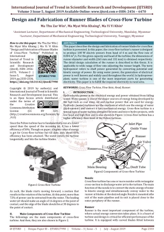
International Journal of Trend in Scientific Research and Development (IJTSRD) @ www.ijtsrd.com eISSN: 2456-6470 C.Types of Hydropower Plants There are different types of Hydro Power Plants based on types of facilities for the generation of hydropower. Construction of large Hydropower Plants is a practical and economically viable proposition as the capital costs of a project can be reduced with such installations. Hydropower Plants may be classified in different ways depending on the certain classification. They are 1.Reservoir or Storage Type 2.Run-of-River Type 3.Pumped Storage Type D.Main Components of Francis Turbine Francis Turbines are the medium head type of hydraulic turbines, having stationary (Spiral casing, Stay Vanes and Guide Vanes) and rotating component. There are several components of Francis Turbine. They are 1.Spiral casing 2.Stay ring 3.Guide vanes 4.Runner 5.Draft tube 6.Shaft Table1.Turbine Selection (Head-Output) Turbine Types Head(m) Horizontal Shaft Pelton Vertical Shaft Pelton Horizontal Shaft Francis Vertical Shaft Francis Cross Flow 7.5 ~ 100 Kaplan 10 ~ 70 Conduit Type Bulb Package Type Bulb Effective Power Output(kW) Over 75 100 ~ 5000 Over 200 Over 4000 17 ~ 300 400 ~ 5000 40 ~ 300 2000 ~ 20000 50 ~ 1000 Over 100 5 ~ 20 Over 1000 5 ~ 18 150 ~ 4000 Table2. Relation between Water Temperature and Standard Stream Pressure Water Temperature ( C) 0 5 10 15 20 Saturated Steam Pressure (m) 0.05 0.09 0.13 0.17 0.24 Table3. The relation between Elevation and Atmospheric Pressure Elevation(m) Pressure (Atm) 0 100 200 300 400 500 600 700 800 900 1000 1100 1200 10.33 10.21 10.09 9.97 9.35 9.73 9.52 9.50 9.39 9.27 9.16 9.05 8.94 Figure1. Francis Turbines III. Francis Turbines can be arranged in two ways; with vertical shaft and horizontal shaft. The vertical shaft arrangement requires the minimum space for installation and therefore permits the smallest area powerhouse. It is not only more economical in space, but in many cases, it is the only practical solution for large machines, especially when the topographical nature of the site limits the size of the powerhouse. By setting of the turbine is meant the location with respect to the head and tailwater level. Referring to Figure3.4 and equating the energies of flow at the exit end of the runner to the energy of flow at the exit end of the draft tube. The result of the various condition of head, speed and capacity are that runner of low speed and capacity are generally demanded under the high head, while runner of high speed and capacity are necessary under the low head. Design Theory of Francis Turbine A.The efficiency of Francis Turbine The expression for the power delivered to the shaft by passing water is the same for all type of reaction turbines. In this case, it is necessary to use velocity diameter and moment of momentum equation (Euler’s Equation) to calculate the power and efficiency of the inward flow turbine. As an assumption, it must be assumed that friction is neglected and fluid has the guidance through the turbine. That is, the infinite number of vanes and relative velocity of the fluid is always tangent to the vane, Steady and one- dimensional flow concept is used for calculation. P = Elemental mass x Tangential velocity P = Similarly, T = T = tT = d V cosα r m 1 1 1 d V cosα r 2 m 2 cosα cosα 1 1 2 r V d m (V (V 1 ) r m m 2 1 r 2 coscosα r ) 1 1 2 2 2 @ IJTSRD | Unique Paper ID – IJTSRD26412 | Volume – 3 | Issue – 5 | July - August 2019 Page 636
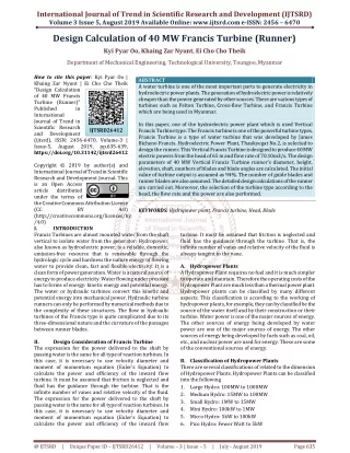
International Journal of Trend in Scientific Research and Development (IJTSRD) @ www.ijtsrd.com eISSN: 2456-6470 Power equation is Power = Torque Angular Velocity cosα (V m 1 α cos V = U = 1 1 U & ω r From above the relations, the equation of power is Power = Above equation can be changed by UV Where, h is hydraulic efficiency of turbine. B.P A.Low-Speed Runner B.Medium Speed Runner C.High-Speed Runner D.High Speed- High Capacity Runner C. The setting of Turbine Draft Head By setting of the turbine is meant the location with respect to the head and tailwater level. Referring to and equating the energies of flow at the exit end of the runner to the energy of flow at the exit end of the draft tube. V W = Where, H = Energy lost in friction during the passage of water through the draft tube H = Elevation of existing of the runner through the draft tube Z = height of runner bottom above any assumed datum P2 =Pressure of exit section of runner Pa = Atmospheric pressure Since the flow through the draft tube is turbulent, the friction r V cosα r )ω Power = 1 1 2 2 2 V & V cosα V w1 2 2 r w2 1 1 ω 2 2 2 1 (V m U ) w1 1 2 f P V 2 2 P a w1 Z H 2 Z Hs η 1 gH W 2g = 2g m d 1 W UV w1 g h = Further the overall efficiency is, 0 η = h m η B.P 1 η U V 1 w1 W gH UV 0 η = d w1 g B.P 2 2 V. Also, velocities at the 0 η = W = γ.Q in the draft tube is proportional to various section of the draft tube are proportional to V2 since the profile of flow is fixed. Thus, p2 = Where, V ( H WH d B.P η γQH 0 = d 2 2 P V Where, B.P = Power of the turbine in kW 0 η =Overall efficiency Q = Flow rate through the turbine in λ = Specific weight of water in kN/ H = Design head in m B.Runner Design as Affected by Speed and Capacity Head and available rate of flow varies widely among power plant. Generally, large flow rates accompany with low head relatively small rates of flow are available at high heads. Because of the difference in flow rates, low head usually requires runner of large water capacity and high head required runner of low capacity. Accordingly, the runner may be again classified as being of high, low and medium capacity, and the term may refer to either the discharge rate or the power output since the latter is a function of the discharge. a H (1 K) s W 2g W 2 2 1 ) 2g m3 /sec 2 2 V ( ) 3 m 2g K = dη = efficiency of the draft tube d 2 2 V H H η 2g H = Where, σ = Thoma’s cavitation coefficient a s d 2 Figure3. Static Draft Head and Various Type of Turbines D.Specific Speed Limit of Specific Speed, N 25 H Calculate Specific Speed, after decided the rated speed, Specific Speed, 21000 35 sl Figure2. Types of Runner @ IJTSRD | Unique Paper ID – IJTSRD26412 | Volume – 3 | Issue – 5 | July - August 2019 Page 637
International Journal of Trend in Scientific Research and Development (IJTSRD) @ www.ijtsrd.com eISSN: 2456-6470 IV. Result Data 1 N = N P 2 t(i) s Table5. Result Data 5 H 4 Descriptions Symbols U1 U2 V1 V2 Vf1 Vf2 Vw1 Vw2 Vr1 Vr2 α1 α2 β1 β2 Pt PG D1 D2 B1 B2 D3 Ds Z - Hs N Ns Nr Nc t Values 27.48 40.05 21.42 5.61 10.95 5.61 18.4 0 13.3 40.41 3075 90 130 7.97 42.75 42 2.1 3.1 0.97 1.3 3.22 0.8 16 24 -6 250 280 486 972 94 Units m/s m/s m/s m/s m/s m/s m/s m/s m/s m/s Degree Degree Degree Degree MW MW m m m m m m m rpm m-kW rpm rpm % E.Normal Efficiency η = 1.172 Inlet tangential velocity Outlet tangential velocity Inlet absolute velocity Outlet absolute velocity Inlet flow velocity Outlet flow velocity Inlet whirl flow velocity Outlet whirl flow velocity Inlet relative velocity Outlet relative velocity Runner inlet angle Runner outlet angle Guide vane inlet angle Guidae vane outlet angle Turbine output power Generator Output power Inlet diameter of Runner Outlet diameter of Runner Inlet high of Runner Outlet high of Runner Runner discharge diameter Runner shaft diameter No: of Runner blades No: of guide blades Runner elevation Turbine speed Specific speed Runaway speed Critical speed Efficiency N N s s ( ) 4.344 ( ) 82.321 n 100 100 . 2 ( i (N Maximum Efficiency, = 08 log P . 4 61 max (N × th t ) 2 Speed factor, u= - 4.4 /100) + 0.039 × /100) + 0.695 s s 1 H 2 Runner inlet diameter, = Runner outlet D 84.6 × K × 1 u N diameter, D = D Runner inlet height, 1 B= [8.7 × D 1 Runner outlet height, 2 B= [0.2875 × D 2 Runner shaft diameter, D s= (863 Inlet peripheral velocity, 1 U= 60 Inlet absolute velocity, V1= g 2 0.6 -2 2 × [-1.7 × 12 (N /100) + 0.44 × (N /100) + 0.321] 2 1 s s -3 2 × 10 (N /100) + 0.15 × (N /100) - 0.028] s s 2 + 0.0175 × (N /100) ] s P t 2 × × N ) πD1 N H Inlet flow velocity, Q V = f1 πD B 1 1 Outlet peripheral velocity, N πD2 Table 6.Comparison of Theory and Actual Data Descriptions Runaway Speed Turbine of Power Outlet Runner Diameter Generation Power Runner Discharge Diameter Shaft Diameter Runner Outlet Height Theory Actual Units 486.4 432.8 42.7 41.24 3.06 2.94 41.89 40 3.22 3.04 0.8 0.7 1.3 = U 2 60 rpm MW m MW m m m Runner inlet angle, V f1 tan α = 1 V w1 Guide vane inlet angle, B= 180° V Theoretical Output Power, P = ρgQH F.Design Input Data The required design data must be known from Thautyegat No.2 Hydroelectric Power Plant, in Bago Division (Myanmar). Table4 .Input Data Descriptions Effective Head Discharge Overall efficiency Output Power of Turbine 1β - 1 1 tan β = f1 V U 1 w1 theo Symbols Value H Q ηo P Unit m m3/s % kW 65 70.10 94 44.7 Figure4. Two Dimensional View of Runner @ IJTSRD | Unique Paper ID – IJTSRD26412 | Volume – 3 | Issue – 5 | July - August 2019 Page 638
International Journal of Trend in Scientific Research and Development (IJTSRD) @ www.ijtsrd.com eISSN: 2456-6470 The runner design is very important for any type of turbine. In this paper, the design calculation of the runner of 40 MW Vertical Francis Turbine which is taken from Thaukyegat No.2 Hydroelectric Power Plant is carried out. This runner is designed in the maximum power output conditions. Any type of turbine, runner blade design is very important. In this paper, the runner blade design of 40MW Francis Turbine is calculated. Acknowledgment Firstly, the author would like to thank my parents for their best wish to join the B.E course at TU(Meiktila). The author greatly expresses her thanks to all persons who will concern to support in preparing this paper. REFERENCES [1]Salman Bahrami, Multi-Fideidy, Design Optimization of Francis Runner Blades, (Dec 2015) Figure5. Three Dimensional View of Runner Discussions and Conclusions Hydropower is contained of two main portions as the mechanical and electrical system. Generally, Francis Turbines are placed in Vertical Francis Turbines configuration. Vertical Francis Turbine is very widely used in the world for large hydroelectric Power plant. [2]Einar Agnalt, Pressure measurements inside a Francis Turbine Runner, (Oct 2014) [3]Kurosawa, Design Optimization Method for Francis Turbine, (Dec 2014) [4]Tun Oke, U, Design and Calculation of Francis Turbine (Runner), (Sept 2009) @ IJTSRD | Unique Paper ID – IJTSRD26412 | Volume – 3 | Issue – 5 | July - August 2019 Page 639