Download
1 / 5
50 likes | 225 Vues
Telecommunication is a very important part of its life. This technology is used in a very sophisticated area like safety and security purpose. Using the GSM technology, telecommunication is conducive to save its life as well as households from fire accidents which have shown in this paper. In this paper, the overall circuit is constructed with six sections. The first section is power supply. The second section is temperature sensor and smoke sensor. The third section is Arduino. The fourth section is LCD display. The fifth section is fan, buzzer and water pump. The sixth section is GSM module. Temperature sensor is connected to the digital input pin of the Arduino and smoke sensor is connected to the analog input pin of the Arduino. When the temperature sensor detects heat and the smoke detector detects smoke the detectable measurement of smoke can be configured regarding the size and surroundings of the room , there is a LCD display which shows temperature and smoke data. When the temperature reach above 40u00c2u00b0C and the smoke sensor had reached over 200ppm, the buzzer is ON, spray automatically water and send SMS. Khin Thandar Tun | Aye Sandar Aung | May Lwin Thant "GSM Based Fire Security System" Published in International Journal of Trend in Scientific Research and Development (ijtsrd), ISSN: 2456-6470, Volume-3 | Issue-5 , August 2019, URL: https://www.ijtsrd.com/papers/ijtsrd26697.pdf Paper URL: https://www.ijtsrd.com/engineering/electronics-and-communication-engineering/26697/gsm-based-fire-security-system/khin-thandar-tun<br>

E N D
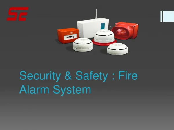
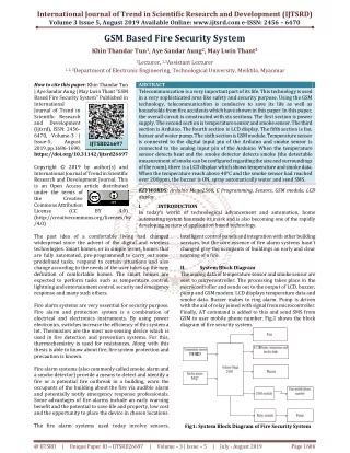
International Journal of Trend in Scientific Research and Development (IJTSRD) Volume 3 Issue 5, August 2019 Available Online: www.ijtsrd.com e-ISSN: 2456 – 6470 GSM Based Fire Security System Khin Thandar Tun1, Aye Sandar Aung2, May Lwin Thant3 1Lecturer, 2,3Assistant Lecturer 1, 2, 3Department of Electronic Engineering, Technological University, Meiktila, Myanmar How to cite this paper: Khin Thandar Tun | Aye Sandar Aung | May Lwin Thant "GSM Based Fire Security System" Published in International Journal of Trend in Scientific Research and Development (ijtsrd), ISSN: 2456- 6470, Volume-3 | Issue-5, August 2019, pp.1686-1690, https://doi.org/10.31142/ijtsrd26697 Copyright © 2019 by author(s) and International Journal of Trend in Scientific Research and Development Journal. This is an Open Access article distributed under the terms of the Creative Commons Attribution License (CC (http://creativecommons.org/licenses/by /4.0) The past idea of a comfortable living had changed widespread since the advent of the digital and wireless technologies. Smart homes, or in simple terms, homes that are fully automated, pre-programmed to carry out some predefined tasks, respond to certain situations and also change according to the needs of the user takes up the new definition of comfortable homes. The smart homes are expected to perform tasks such as temperature control, lightning and entertainment control, security and emergency response and many such others. Fire alarm systems are very essential for security purpose. Fire alarm and protection system is a combination of electrical and electronics instruments. By using power electronics, switches increase the efficiency of this system a lot. Thermistors are the most use sensing device which is used in fire detection and prevention systems. For this, thermochemistry is used for resistances. Along with this thesis is able to know about fire, fire system protection and precaution is known. Fire alarm systems (also commonly called smoke alarm and a smoke detector) provide a means to detect and identify a fire or a potential fire outbreak in a building, warn the occupants of the building about the fire via audible alarm and potentially notify emergency response professionals. Some advantages of fire alarms include an early warning benefit and the potential to save life and property, low cost and the opportunity to place the device in chosen locations. The fire alarm systems used today involve sensors, ABSTRACT Telecommunication is a very important part of its life. This technology is used in a very sophisticated area like safety and security purpose. Using the GSM technology, telecommunication is conducive to save its life as well as households from fire accidents which have shown in this paper. In this paper, the overall circuit is constructed with six sections. The first section is power supply. The second section is temperature sensor and smoke sensor. The third section is Arduino. The fourth section is LCD display. The fifth section is fan, buzzer and water pump. The sixth section is GSM module. Temperature sensor is connected to the digital input pin of the Arduino and smoke sensor is connected to the analog input pin of the Arduino. When the temperature sensor detects heat and the smoke detector detects smoke (the detectable measurement of smoke can be configured regarding the size and surroundings of the room), there is a LCD display which shows temperature and smoke data. When the temperature reach above 40°C and the smoke sensor had reached over 200ppm, the buzzer is ON, spray automatically water and send SMS. KEYWORDS: Arduino Mega2560, C Programming, Sensors, GSM module, LCD display I. INTRODUCTION In today’s world of technological advancement and automation, home automating system has made its mark and is also becoming one of the rapidly developing sectors of application based technology. intelligent control panels and integration with other building services, but the core essence of fire alarm systems hasn’t changed give the occupants of buildings an early and clear warning of a fire. II. System Block Diagram The analog data of temperature sensor and smoke sensor are sent to microcontroller. The processing takes place in the microcontroller and sends out to the output of LCD, buzzer, pump and GSM modem. LCD displays temperature data and smoke data. Buzzer makes to ring alarm. Pump is driven with the aid of relay joined with signal from microcontroller. Finally, AT command is added to this and send SMS from GSM to user mobile phone number. Fig.1 shows the block diagram of fire security system. IJTSRD26697 BY 4.0) Fig1: System Block Diagram of Fire Security System @ IJTSRD | Unique Paper ID – IJTSRD26697 | Volume – 3 | Issue – 5 | July - August 2019 Page 1686
International Journal of Trend in Scientific Research and Development (IJTSRD) @ www.ijtsrd.com eISSN: 2456-6470 The flowchart shown in Fig.2 is for the operation of the system. The algorithm used in the flow chart. ?Step 1: Start. ?Step 2: Read temperature sensor and smoke sensor. ?Step 3: Check the temperature value between 30ºC and 35ºC ?Step 4: Check the temperature value between 36ºC and 40ºC ?Step 5: Check the temperature and smoke sensor reach above 40ºC and 200rpm ?Step 6: After the fan rotate with 200 between the temperature 30ºC and 35ºC. At the temperature, the buzzer does not ring the alarm and water does not spray. ?Step 7: The fan rotates with 250 between the temperature 36ºC and 40ºC. At the temperature, the buzzer does not ring the alarm and water does not spray. ?Step 8: When the temperature and smoke sensor reach above 40ºC and 200, the fan does not rotate, the buzzer ring the alarm, spray water automatically and send SMS from GSM to phone number of user mobile. ?Step 9: The fan rotates with 100rpm below 30ºC. At the temperature, the buzzer will not ring the alarm and water does not spray. ?Step10: End. programming language, but uses built-in libraries to simplify complicated coding tasks to make it easier for beginners to pick up. The Arduino language is an open source. One aim of the IDE is to reduce the configuration necessary to piece together multiple development utilities, instead providing the same set of capabilities as a cohesive unit. The functions of each button on IDE toolbar are shown in Table 1. Fig3: Arduino IDE Table1. Functions of Toolbar Buttons Button Verify or Compile convert machine code Stop Stop the serial monitor New Creates a new blank sketch Shows a list of sketches in sketchbook Save Save the current sketch Upload Upload the current sketch to Arduino Serial Monitor Arduino Functions Checks the code for errors and Open Displays serial data sending from After the temperature sensor is interfaced with Arduino, the required program shown in Fig.4 for temperature is written on the Arduino IDE. Firstly, library file and address for DS18B20 is defined and register in this DS18B20 is set to read one wire bus value. And then, pin of Arduino is assigned for DS18B20 and are defined what pin is digitalpin. And then, the code is written for temperature. To do an explanation of the code, as usual, it go to the OneWire.h library. #include<OneWire.h > Finally, the required temperature is converted from float temperature by using sensors.getTempCByIndex(0);” equation and the unit of this distance is described in degree. float temp= sensors.getTempCByIndex(0); “float temp= Fig2: Flowchart of the system. III. A.Implementation using Arduino Mega2560 The software for programming an Arduino is easy to use and also freely available for Windows, Mac, and Linux computer at no cost. The Arduino software which is shown in Fig.3 is referred to as an Integrated Development Environment (IDE). This is the programming software that is used to upload code to the Arduino microcontroller. The IDE is divided into three main areas: the command area, the text area, and the message window area. The IDE also transfers those instructions to the Arduino board (a process called uploading). The Arduino language is a variant of the C++ Implementation Fig4: Testing Program for Temperature Sensors @ IJTSRD | Unique Paper ID – IJTSRD26697 | Volume – 3 | Issue – 5 | July - August 2019 Page 1687
International Journal of Trend in Scientific Research and Development (IJTSRD) @ www.ijtsrd.com eISSN: 2456-6470 Then, C program language for MQ-7 is defined and register in the MQ-7 is set to read integer value. The program required which is shown in Fig.5. The MQ-7 is coded to know smoke detection. Finally, pin of Arduino is assigned for MQ-7 and are defined what pin is analog (A1) pin. B.Implementation by Hardware 1.GSM based Fire Security System To implement GSM based fire security system, all of sensors, relay driver, GSM module, AC motor pump, fan, buzzer and microcontroller are interfaced as shown Fig. 8. Temperature sensor is connected to the Arduino of the digital input pin. Temperature sensor always read the temperature. Smoke sensor is connected to the Arduino of the Analog input pin. Smoke sensor always senses vapours. All data from which are sent to Arduino for processing. The outputs that get from Arduino are used to make the rounds of fan, show with LCD display and spray with water automatically, send the message from GSM to user mobile phone number. Making the rounds of fan depend on temperature sensor. At the room temperature of below 30ºC, the fan starts to run with 100rpm.The fan rounds 200rpm between30°C ≤ T > 35 °C and 250rpm between 36 °C ≤ T >40 °C. The fan stops rounding when the temperature reaches above 40°C. If the fan stops, the smoke sensor begins to work. When the temperature and the gas reach above 40°C and 200rpm, the buzzer rings the alarm, spray water automatically and sends SMS from GSM to phone number of user mobile. Fig5: Testing Program for Smoke Sensor And then, LiquidCrystal_I2C function sets the dimensions of the LCD. It needs to be placed before any other LiquidCrystal function in the void setup() section of the program. The number of rows and columns are specified as lcd.begin (columns, rows). For 16x2 LCD, lcd.begin (16,2) can be seen, and for a 20x4 LCD, lcd.begin (20,4) can be used. The backlight is also be turned on and off with lcd.setBacklight (HIGH) or lcd.setBacklight (LOW). Fig6: Testing Program for LCD To get target message, SIM900A GSM module is selected. Therefore, program which is shown in Fig.7 is written for GSM module to read message. Firstly, library file for GSM module is defined and pins of Arduino are assigned for GSM module and then define what pins are transmitted pin and received pin. To do an explanation of the code, as usual, the first thing do is include the libraries the SoftareSerial.h library. #include <SoftwareSerial.h> Fig8: Overall Circuit Diagram of the system 2.Power Supply Section Fig9: Power Supply Fig7: Testing Program for GSM Module @ IJTSRD | Unique Paper ID – IJTSRD26697 | Volume – 3 | Issue – 5 | July - August 2019 Page 1688
International Journal of Trend in Scientific Research and Development (IJTSRD) @ www.ijtsrd.com eISSN: 2456-6470 Power supply is one of the main parts of this system. 220V to 12V step down transformer is used to reduce 12V AC in transformer’s secondary. The four rectifier diodes (1N4007) make to convert DC (Direct Current). DC from a full wave rectifier diode isn’t smooth to use. So, 1000µF capacitor is used to filter ripple. And then, 7805 (5V regulator IC) is used to produce 5V stable voltage. 7805 pin out connects to GSM module VCC and GND pin for GSM module GND. This circuit uses 5V adapter for Arduino board. 5V from Arduino board is used for temperature sensor, smoke sensor and 16x2 LCD supply. IV. Results Before program is uploaded to Arduino, temperature sensor DS18B20 is interfaced with Arduino. When power is on, DSI8B20 initializes to read temperature simultaneously. This data can be watched in serial monitor on Arduino IDE as shown in Fig.10. The fan rotates with 100rpm below 30˚C. At the temperature, the buzzer does not ring the alarm, water does not spray and message is not sent. The fan rotates with 200rpm between the temperature 30˚C and 35˚C. At the temperature, the buzzer does not ring the alarm, water does not spray and message is not sent. The fan rotates with 250rpm between the temperature 36˚C and 40˚C. At the temperature, the buzzer does not ring the alarm, water does not spray and message is not sent. Fig 13: Rotation of Fan with 250rpm between temperature 36Cº and 40Cº When the temperature reaches above 40˚C, the fan will stop. After the smoke sensor had reached over 200, the buzzer rings the alarm, spray water automatically and send SMS. Fig10: Displaying Temperature Sensor on Serial Monitor After interfacing smoke sensor with Arduino, the required program is coded into Arduino and then smoke sensor detects vapours immediately when power is on. Fig14: Testing for Sending Message V. The paper describes the use of microcontroller in the development of the GSM based home security system which detects and prevents various accidents by warning the person responsible in the right time. Various accidents occurring due to fire and LPG leakage can be prevented by incorporating the above paper in the homes. Along with these protections from criminal activities like theft, robbery can also be prevented. Arduino Mega2560 board is used as a microcontroller and interfaced serially to GSM modem. The program is written in the internal memory of ATmega2560 microcontroller of Arduino board. Integrated Development Environment (IDE) software is used to install the program in it. The program for Adriano board can be written by C programming language. VI. Conclusion This circuit uses the GSM module for receiving signal from an Arduino. They have designed and developed the whole control system and tested using smoke detector. They fix all Discussion Fig11: Displaying Smoke Data on Serial Monitor Before program is uploaded to Arduino, 16x2 LCD display is interfaced with Arduino. When power is on, 16x2 LCD display initializes to display temperature and smoke simultaneously. Fig12: 16x2 LCD Display @ IJTSRD | Unique Paper ID – IJTSRD26697 | Volume – 3 | Issue – 5 | July - August 2019 Page 1689
International Journal of Trend in Scientific Research and Development (IJTSRD) @ www.ijtsrd.com eISSN: 2456-6470 [4]Anonymous.: http://www.maximintegrated.com the problems encountered during the design and testing of the system. Finally, it successfully achieved their goals. In this study, the application of microcontroller with improved algorithm of extended specification has increased the use of GSM shield and improves the controlling the smoke. GSM communication has been designed and developed for making their life easier and secured. So, fire alarm system using GSM communication is suitable. VII. REFERENCES [1]Anonymous.: “Fan https://www.techadvisor.com “Temperature Sensor”, (2018), [5]Amelia, R.: “Sims 900A GSM module, February (2015), http://www.sim.com [6]Brian, E.: “Arduino introduction”, May (2013), http://www.arduino.com [7]Alexey, P.: “Connecting GSM Sims900A module with Arduino”. http://www.electronics.stackexchange.com March, (2011) Speed”, (2018), [8]Chinonzo, E.: “Introduction to GSM”. April, (2011) http://www.karimsalih.6te.net [2]Anonymous.: https://www.instructables.com “LCD Display”, (2018), [9]Bharath, Vijay K., Anil R., Abhishek: “Vehicle Tracking System using GSM”, (1998). [3]Anonymous.: http://www.instructables.com “Smoke Senor”, (2018), [10]Kernigham, B.W., Ritchie, D.; M.: The C Programming language, Prentice Hall, (1988). @ IJTSRD | Unique Paper ID – IJTSRD26697 | Volume – 3 | Issue – 5 | July - August 2019 Page 1690