Download
1 / 3
30 likes | 126 Vues
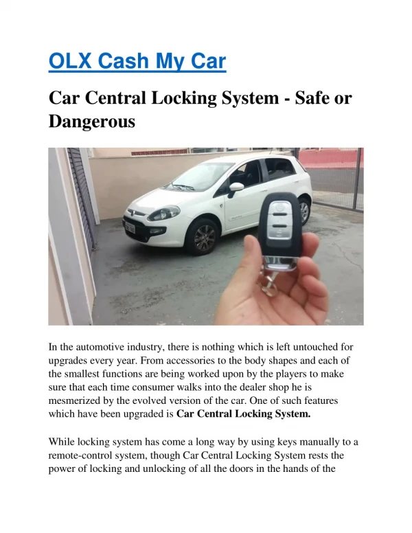
Headlights aren't the most complicated tech, even in newer cars with fancy systems like adaptive headlights, but there are a handful of different points of failure that could result in the situation that it describing. The easiest way to keep the battery from dying is to straight up disconnect it. If it never done that before, then it'll just want to make sure that it disconnect the negative cable typically black instead of the positive cable typically red to avoid even the possibility of a short circuit. Once the battery is disconnected, the headlights will turn off, and the battery won't die. The other way to shut the headlights off is to remove the appropriate fuse or relay. This is a little more complicated than disconnecting the battery since you will have to locate the correct fuse panel and then figure out which fuse or relay to pull. It will prevent a loss of power to the computer and radio, though, so you won't have to deal with any fallout later on. Dr. S Senthil Kumar | Sathiyaprakash K | Vijay R | Sudharsan D "Automatic Headlight Control with Central Locking System" Published in International Journal of Trend in Scientific Research and Development (ijtsrd), ISSN: 2456-6470, Volume-2 | Issue-2 , February 2018, URL: https://www.ijtsrd.com/papers/ijtsrd8217.pdf Paper URL: http://www.ijtsrd.com/engineering/electrical-engineering/8217/automatic-headlight-control-with-central-locking-system/dr-s-senthil-kumar<br>

E N D
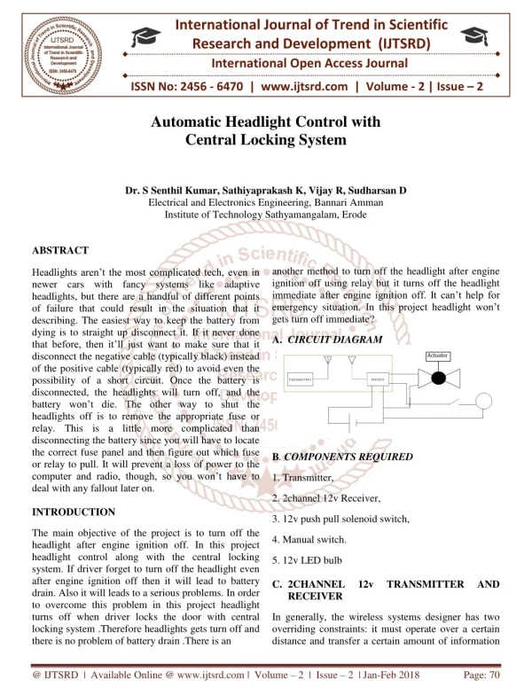
International Journal of Trend in Scientific Research and Development (IJTSRD) International Open Access Journal ISSN No: 2456 - 6470 | www.ijtsrd.com | Volume - 2 | Issue – 2 Automatic Headlight Control with Central Locking System Dr. S Senthil Kumar, Sathiyaprakash K, Vijay R, Sudharsan D Electrical and Electronics Engineering, Bannari Amman Institute of Technology Sathyamangalam, Erode ABSTRACT Headlights aren’t the most complicated tech, even in newer cars with fancy systems like adaptive headlights, but there are a handful of different points of failure that could result in the situation that it describing. The easiest way to keep the battery from dying is to straight up disconnect it. If it never done that before, then it’ll just want to make sure that it disconnect the negative cable (typically black) instead of the positive cable (typically red) to avoid even the possibility of a short circuit. Once the battery is disconnected, the headlights will turn off, and the battery won’t die. The other way to shut the headlights off is to remove the appropriate fuse or relay. This is a little more complicated than disconnecting the battery since you will have to locate the correct fuse panel and then figure out which fuse or relay to pull. It will prevent a loss of power to the computer and radio, though, so you won’t have to deal with any fallout later on. INTRODUCTION another method to turn off the headlight after engine ignition off using relay but it turns off the headlight immediate after engine ignition off. It can’t help for emergency situation. In this project headlight won’t gets turn off immediate? A.CIRCUIT DIAGRAM B. COMPONENTS REQUIRED 1. Transmitter, 2. 2channel 12v Receiver, 3. 12v push pull solenoid switch, The main objective of the project is to turn off the headlight after engine ignition off. In this project headlight control along with the central locking system. If driver forget to turn off the headlight even after engine ignition off then it will lead to battery drain. Also it will leads to a serious problems. In order to overcome this problem in this project headlight turns off when driver locks the door with central locking system .Therefore headlights gets turn off and there is no problem of battery drain .There is an 4. Manual switch. 5. 12v LED bulb C.2CHANNEL RECEIVER 12v TRANSMITTER AND In generally, the wireless systems designer has two overriding constraints: it must operate over a certain distance and transfer a certain amount of information @ IJTSRD | Available Online @ www.ijtsrd.com | Volume – 2 | Issue – 2 | Jan-Feb 2018 Page: 70
International Journal of Trend in Scientific Research and Development (IJTSRD) ISSN: 2456-6470 within a data rate. The RF modules are very small in dimension and have a wide operating voltage range i.e. 3V to 12V. Basically the RF modules are 433 MHz RF transmitter and receiver modules. The transmitter draws no power when transmitting logic zero while fully suppressing the carrier frequency thus consume significantly low power in battery operation. When logic one is sent carrier is fully on to about 4.5mA with a 3volts power supply. The data is sent serially from the transmitter which is received by the tuned receiver. Transmitter and the receiver are duly interfaced to two microcontrollers for data transfer. In many projects we use RF modules for transmit and receive the data because it has high volume of applications than IR. RF signals travel in the transmitter and receiver even when there is an obstruction. It operates at a specific frequency of 433MHz. RF transmitter receives serial data and transmits to the receiver through an antenna which is connected to the 4th pin of the transmitter. When logic 0 applied to transmitter then there is no power supply in transmitter. When logic 1 is applied to transmitter then transmitter is ON and there is a high power supply in the range of 4.5mA with 3V voltage supply. D.CIRCUIT DIAGRAM DESCRIPTION FEATURES OF RF MODULE: • Receiver frequency 433MHz • Receiver typical frequency 105Dbm • Receiver supply current 3.5mA • Low power consumption • Receiver operating voltage 5v • Transmitter frequency range 433.92MHz • Transmitter supply voltage 3v~6v • Transmitter output power 4v~12v In this project, Signal is transmitted from the Transmitter and Receiver receives it through Antenna. 2CH Receiver is connected with the 12volt push pull solenoid switch and the Headlight. A Manual switch is connected between the Headlight and the Receiver. If the Receiver receives the Signal both Solenoid switch and Headlight works parallely. During ON signal from the Transmitter, Headlight get turns on and Solenoid switch gets pull, thus door will unlock. If Headlight is not required it will control with Manual switch. While Signal cutoff from the Transmitter, Solenoid switch gets push, thus door will lock. E.TRANSMITTER-RECEIVER INTERFACING A wireless radio frequency (RF) transmitter and receiver can be using HT12D Decoder, HT12E Encoder and ASK RF Module. Wireless transmission can be done by using 433Mhz or 315MHz ASK RF Transmitter and Receiver modules. In these modules digital data is represented by different amplitudes of the carrier wave, hence this modulation is known as Amplitude Shift Keying (ASK). Radio Frequency (RF) transmission is more strong and reliable than Infrared (IR) transmission due to following reasons: easily made Transmitter circuit •Radio Frequency signals can travel longer distances than Infrared. •Only line of sight communication is possible through Infrared while radio frequency signals can be transmitted even when there is obstacles •Infrared signals will get interfered by other IR sources but signals on one frequency band in RF will not interfered by other frequency RF signals. Receiver circuit @ IJTSRD | Available Online @ www.ijtsrd.com | Volume – 2 | Issue – 2 | Jan-Feb 2018 Page: 71
International Journal of Trend in Scientific Research and Development (IJTSRD) ISSN: 2456-6470 HT12E Encoder IC will convert the 4 bit parallel data given to pins D0 – D3 to serial data and will be available at DOUT. This output serial data is given to ASK RF Transmitter. Address inputs A0 – A7 can be used to provide data security and can be connected to GND (Logic ZERO) or left open (Logic ONE). Status of these Address pins should match with status of address pins in the receiver for the transmission of the data. Data will be transmitted only when the Transmit Enable pin (TE) is LOW. 1.1MΩ resistor will provide the necessary external resistance for the operation of the internal oscillator of HT12E.ASK RF Receiver receives the data transmitted using ASK RF Transmitter. HT12D decoder will convert the received serial data to 4 bit parallel data D0 – D3. The status of these address pins A0-A7 should match with status of address pin in the HT12E at the transmitter for the transmission of data. The LED connected to the above circuit glows when valid data transmission occurs from transmitter to receiver. 51KΩ resistor will provide the necessary resistance required for the internal oscillator of the HT12D. F.HARDWARE IMPLEMENTATION If driver forget to turn off the headlight even after engine ignition off then it will lead to battery drain. Also it will leads to a serious problems. In order to overcome this problem in this project headlight turns off when driver locks the door with central locking system .Therefore headlights gets turn off and there is no problem of battery drain .There is an another method to turn off the headlight after engine ignition off using relay but it turns off the headlight immediate after engine ignition off. It can’t help for emergency situation. In this project headlight won’t gets turn off immediate? G.FUTURE SCOPE This project can developed into next stage by making light dimmer and intensity adjustment automatically along with the central locking system. H.CONCLUSION Battery drain can be saved easily by using this experiment. Main thing in this experiment is time required is less. Hence it is easy to invest. From this project, the problem faced by the drivers can overcome easily due to the operation of headlight along with the central locking system REFERENCES 1.Electronic Devices and Circuits – Dr. K. Lal Kishore, B.S. Publications, 2nd Edition, 2005. 2.Analog Electronics. Authors- MAHESWARI, M.M.S.ANAND.2009. L.K. @ IJTSRD | Available Online @ www.ijtsrd.com | Volume – 2 | Issue – 2 | Jan-Feb 2018 Page: 72