Download
1 / 11
110 likes | 128 Vues
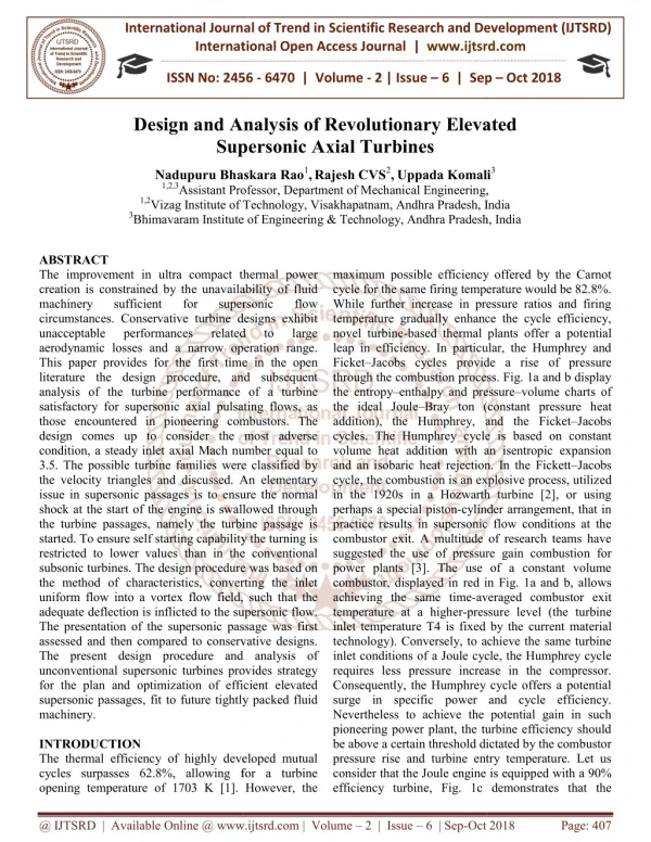
The improvement in ultra compact thermal power creation is constrained by the unavailability of fluid machinery sufficient for supersonic flow circumstances. Conservative turbine designs exhibit unacceptable performances related to large aerodynamic losses and a narrow operation range. This paper provides for the first time in the open literature the design procedure, and subsequent analysis of the turbine performance of a turbine satisfactory for supersonic axial pulsating flows, as those encountered in pioneering combustors. The design comes up to consider the most adverse condition, a steady inlet axial Mach number equal to 3.5. The possible turbine families were classified by the velocity triangles and discussed. An elementary issue in supersonic passages is to ensure the normal shock at the start of the engine is swallowed through the turbine passages, namely the turbine passage is started. To ensure self starting capability the turning is restricted to lower values than in the conventional subsonic turbines. The design procedure was based on the method of characteristics, converting the inlet uniform flow into a vortex flow field, such that the adequate deflection is inflicted to the supersonic flow. The presentation of the supersonic passage was first assessed and then compared to conservative designs. The present design procedure and analysis of unconventional supersonic turbines provides strategy for the plan and optimization of efficient elevated supersonic passages, fit to future tightly packed fluid machinery. Nadupuru Bhaskara Rao | Rajesh CVS | Uppada Komali "Design and Analysis of Revolutionary Elevated Supersonic Axial Turbines" Published in International Journal of Trend in Scientific Research and Development (ijtsrd), ISSN: 2456-6470, Volume-2 | Issue-6 , October 2018, URL: https://www.ijtsrd.com/papers/ijtsrd18481.pdf Paper URL: http://www.ijtsrd.com/engineering/mechanical-engineering/18481/design-and-analysis-of-revolutionary-elevated-supersonic-axial-turbines/nadupuru-bhaskara-rao<br>

E N D
International Journal of Trend in International Open Access Journal International Open Access Journal | www.ijtsrd.com International Journal of Trend in Scientific Research and Development (IJTSRD) Research and Development (IJTSRD) www.ijtsrd.com ISSN No: 2456 ISSN No: 2456 - 6470 | Volume - 2 | Issue – 6 | Sep 6 | Sep – Oct 2018 Design and Analysis Supersonic Axial Turbines Supersonic Axial Turbines nd Analysis of Revolutionary Elevated f Revolutionary Elevated Nadupuru Bhaskara Rao1,Rajesh CVS2,Uppada Komali Assistant Professor, Department of Mechanical Engineering, Vizag Institute of Technology, Visakhapatnam, Andhra Pradesh, India Vizag Institute of Technology, Visakhapatnam, Andhra Pradesh, India Uppada Komali3 Nadupuru Bhaskara Rao 1,2,3Assistant Professor 1,2Vizag Institute of Technology, Visakhapatnam, Andhra Pradesh, India 3Bhimavaram Institute of Engineering & Technology, Andhra Pradesh, India Bhimavaram Institute of Engineering & Technology, Andhra Pradesh, India Bhimavaram Institute of Engineering & Technology, Andhra Pradesh, India , ABSTRACT The improvement in ultra compact thermal power creation is constrained by the unavailability of fluid machinery sufficient circumstances. Conservative turbine designs exhibit unacceptable performances aerodynamic losses and a narrow operation range. This paper provides for the first time in the open literature the design procedure, and subsequent analysis of the turbine performance of a turbine satisfactory for supersonic axial pulsating flows, as those encountered in pioneering combustors. The design comes up to consider the most adverse condition, a steady inlet axial Mach number equal to 3.5. The possible turbine families were classified by the velocity triangles and discussed. An elementary issue in supersonic passages is to ensure the normal shock at the start of the engine is swallowed through the turbine passages, namely the turbine passage is started. To ensure self starting capability the turning is restricted to lower values than in the conventional subsonic turbines. The design procedure was based on the method of characteristics, converting the inlet uniform flow into a vortex flow field, such that the adequate deflection is inflicted to the supersonic flow. The presentation of the supersonic passage was first assessed and then compared to conservative designs. The present design procedure and analysis of unconventional supersonic turbines provides strategy for the plan and optimization of efficient elevated supersonic passages, fit to future tightly packed fluid machinery. INTRODUCTION The thermal efficiency of highly developed mutual cycles surpasses 62.8%, allowing for a turbine opening temperature of 1703 K [1]. However, the opening temperature of 1703 K [1]. However, the maximum possible efficiency offered by the Carnot cycle for the same firing temperature would be 82.8%. While further increase in pressure ratios and firing temperature gradually enhance the cycle efficiency, novel turbine-based thermal plants offer a pote leap in efficiency. In particular, the Humphrey and Ficket–Jacobs cycles provide a rise of pressure through the combustion process. Fig. 1a and b display the entropy–enthalpy and pressure the ideal Joule–Bray ton (constant pressure h addition), the Humphrey, and the Ficket cycles. The Humphrey cycle is based on constant volume heat addition with an isentropic expansion and an isobaric heat rejection. In the Fickett cycle, the combustion is an explosive process, utiliz in the 1920s in a Hozwarth turbine [2], or using perhaps a special piston-cylinder arrangement, that in practice results in supersonic flow conditions at the combustor exit. A multitude of research teams have suggested the use of pressure gain combustio power plants [3]. The use of a constant volume combustor, displayed in red in Fig. 1a and b, allows achieving the same time-averaged combustor exit temperature at a higher-pressure level (the turbine inlet temperature T4 is fixed by the current mater technology). Conversely, to achieve the same turbine inlet conditions of a Joule cycle, the Humphrey cycle requires less pressure increase in the compressor. Consequently, the Humphrey cycle offers a potential surge in specific power and cycle efficien Nevertheless to achieve the potential gain in such pioneering power plant, the turbine efficiency should be above a certain threshold dictated by the combustor pressure rise and turbine entry temperature. Let us consider that the Joule engine is equipp efficiency turbine, Fig. 1c demonstrates that the efficiency turbine, Fig. 1c demonstrates that the improvement in ultra compact thermal power creation is constrained by the unavailability of fluid machinery sufficient circumstances. Conservative turbine designs exhibit unacceptable performances d a narrow operation range. This paper provides for the first time in the open literature the design procedure, and subsequent analysis of the turbine performance of a turbine satisfactory for supersonic axial pulsating flows, as maximum possible efficiency offered by the Carnot cycle for the same firing temperature would be 82.8%. While further increase in pressure ratios and firing temperature gradually enhance the cycle efficiency, based thermal plants offer a potential leap in efficiency. In particular, the Humphrey and Jacobs cycles provide a rise of pressure through the combustion process. Fig. 1a and b display enthalpy and pressure–volume charts of ton (constant pressure heat addition), the Humphrey, and the Ficket–Jacobs cycles. The Humphrey cycle is based on constant volume heat addition with an isentropic expansion and an isobaric heat rejection. In the Fickett–Jacobs cycle, the combustion is an explosive process, utilized in the 1920s in a Hozwarth turbine [2], or using cylinder arrangement, that in practice results in supersonic flow conditions at the combustor exit. A multitude of research teams have suggested the use of pressure gain combustion for power plants [3]. The use of a constant volume combustor, displayed in red in Fig. 1a and b, allows for for supersonic supersonic flow flow related related to to large large ering combustors. The design comes up to consider the most adverse condition, a steady inlet axial Mach number equal to 3.5. The possible turbine families were classified by the velocity triangles and discussed. An elementary s to ensure the normal shock at the start of the engine is swallowed through the turbine passages, namely the turbine passage is started. To ensure self starting capability the turning is restricted to lower values than in the conventional s. The design procedure was based on the method of characteristics, converting the inlet uniform flow into a vortex flow field, such that the adequate deflection is inflicted to the supersonic flow. The presentation of the supersonic passage was first ssed and then compared to conservative designs. The present design procedure and analysis of unconventional supersonic turbines provides strategy for the plan and optimization of efficient elevated supersonic passages, fit to future tightly packed fluid averaged combustor exit pressure level (the turbine inlet temperature T4 is fixed by the current material technology). Conversely, to achieve the same turbine inlet conditions of a Joule cycle, the Humphrey cycle requires less pressure increase in the compressor. Consequently, the Humphrey cycle offers a potential surge in specific power and cycle efficiency. Nevertheless to achieve the potential gain in such pioneering power plant, the turbine efficiency should be above a certain threshold dictated by the combustor pressure rise and turbine entry temperature. Let us consider that the Joule engine is equipped with a 90% The thermal efficiency of highly developed mutual cycles surpasses 62.8%, allowing for a turbine @ IJTSRD | Available Online @ www.ijtsrd.com www.ijtsrd.com | Volume – 2 | Issue – 6 | Sep-Oct 2018 Oct 2018 Page: 407
International Journal of Trend in Scientific Research and Development (IJTSRD) ISSN: 2456 International Journal of Trend in Scientific Research and Development (IJTSRD) ISSN: 2456 International Journal of Trend in Scientific Research and Development (IJTSRD) ISSN: 2456-6470 required efficiency of the turbine in the Humphrey cycle to achieve the same cycle efficiency than the Joule cycle, decreases a function of the combustor pressure rise. Humphrey cycles operati turbine entry temperatures, with low compression ratio require low turbine efficiencies. For instance, in a Humphrey cycle with T4 ¼1500 K, P3/ combustor pressure rise of 40%, a turbine with an isentropic efficiency of 59% would ext work than a 90% efficiency turbine in a Joule cycle. Nomenclature A Area [m2] C Chord [m] E Relative error M Mach number V/ (γ.ℜ.T)1/2 R Grid refinement factor 1,2 Inlet and outlet conditions of a stator row, respectively 2,3 Inlet and outlet conditions of a rotor row, respectively required efficiency of the turbine in the Humphrey cycle to achieve the same cycle efficiency than the Joule cycle, decreases a function of the combustor pressure rise. Humphrey cycles operating at large turbine entry temperatures, with low compression ratio require low turbine efficiencies. For instance, in a Humphrey cycle with T4 ¼1500 K, P3/P2¼5; with a combustor pressure rise of 40%, a turbine with an isentropic efficiency of 59% would extract the same work than a 90% efficiency turbine in a Joule cycle. Inlet and outlet conditions of a stator row, tlet conditions of a rotor row, Figure-1 indicate the Single closed loop Simplified enthalpy enthropy Pressure–volume layout; c) Turbine efficiency in a Humphrey cycle to obtain the same efficiency than a Bray ton cycle with a 90% turbine efficiency.(For interpretation of the references to color in this figure, the reader is referred to the web version of this article.) Supersonic passage designs Single closed loop cycles: a) enthropy representation; b) volume layout; c) Turbine efficiency in a Humphrey cycle to obtain the same efficiency than a ton cycle with a 90% turbine efficiency.(For interpretation of the references to color in this figure, the web version of this Figure- -2 @ IJTSRD | Available Online @ www.ijtsrd.com www.ijtsrd.com | Volume – 2 | Issue – 6 | Sep-Oct 2018 Oct 2018 Page: 408
International Journal of Trend in Scientific Research and Development (IJTSRD) ISSN: 2456 International Journal of Trend in Scientific Research and Development (IJTSRD) ISSN: 2456 International Journal of Trend in Scientific Research and Development (IJTSRD) ISSN: 2456-6470 Above figure shows a passage designed with the “corner flow method”. The front suction side is curved to cancel the incoming compression waves generated along the concave pressure side, followed then by a parallel flow. The flow subsequently corner flow expansion, where waves are canceled by the concave surface, until uniform parallel flow is achieved at the exit. However, the design exhibits zero loading in the central part of the passage, and the flow turning is limited. Above figure shows a passage designed with the “corner flow method”. The front suction side is curved to cancel the incoming compression waves generated along the concave pressure side, followed then by a parallel flow. The flow subsequently experiences a corner flow expansion, where waves are canceled by the concave surface, until uniform parallel flow is achieved at the exit. However, the design exhibits zero loading in the central part of the passage, and the flow turning is limited. Possible in take operating regions shown in Figure3 below, regions shown in Figure3 Supersonic turbines have attracted interest from the industry since the 1950s due to the high specific power they could provide, allowing a reduction in the number of low-pressure stages, and thus leading to lighter turbines together with lower manufacture operational costs. Fig. 2 a depicts three distinct regions in the vane nozzle: a converging (subsonic) section, a diverging (supersonic) section and a straight section in the rear suction surface. To maximize the specific power, the degree of reaction is traditionally very low. The design of such impulse type rotors can be achieved following two different strategies based on the method of characteristics Supersonic turbines have attracted interest from the industry since the 1950s due to the high specific power they could provide, allowing a reduction in the pressure stages, and thus leading to lighter turbines together with lower manufacture and three distinct regions in the vane nozzle: a converging (subsonic) section, a diverging (supersonic) section and a straight section in the rear suction surface. To maximize the specific power, the on is traditionally very low. The design of such impulse type rotors can be achieved following two different strategies based on the State-of-the-art high-pressure-turbine vane passages are characterized by a strong area contraction up to the throat. Consequently, when conventional vanes are exposed to high supersonic inlet Mach numbers turbine vane passages the diffuser is never self-starting. Standing shock waves upstream of the turbine cascade cause large irreversibilities and, in particular, ab dynamic pressure, starting. Standing shock are characterized by a strong area contraction up to the throat. Consequently, when conventional vanes waves upstream of the turbine cascade cause large irreversibilities and, in particular, abatement of the et Mach numbers @ IJTSRD | Available Online @ www.ijtsrd.com www.ijtsrd.com | Volume – 2 | Issue – 6 | Sep-Oct 2018 Oct 2018 Page: 409
International Journal of Trend in Scientific Research and Development (IJTSRD) ISSN: 2456 International Journal of Trend in Scientific Research and Development (IJTSRD) ISSN: 2456 International Journal of Trend in Scientific Research and Development (IJTSRD) ISSN: 2456-6470 An additional problem is the unfavorable pressure gradient across supersonic diffusers that may lead to boundary layer separation, which additionally limits flow turning in the passage. Furthermore, the efficiency of a supersonic turbine is seriously penalized by the existence of flow separation on the suction surface caused by shock–boundary layer interactions. Higher loadings, i.e. higher suction surface Mach numbers and lower pressure surface Mach numbers are desirable for the starting condition as well as to maximize the work produced by the turbine. However, adverse pressure gradients will become much more pronounced within the passage, clearly showing an important compromise between starting conditions and flow separation. The current paper presents an approach to design turbine passages with adequate contraction The performance of these unconventional turbine passages was evaluated numerically using the solver CFDþ þ, both in steady and transient operation, to study the movement of a normal shock wave across the turbine. An additional problem is the unfavorable pressure s supersonic diffusers that may lead to boundary layer separation, which additionally limits flow turning in the passage. Furthermore, the efficiency of a supersonic turbine is seriously penalized by the existence of flow separation on the Procedure of Turbine Design Procedure of Turbine Design boundary layer interactions. Higher loadings, i.e. higher suction surface Mach numbers and lower pressure surface Mach numbers are desirable for the starting condition as well as to maximize the work produced by the e pressure gradients will become much more pronounced within the passage, clearly showing an important compromise between The current paper presents an approach to design turbine passages with adequate contraction area ratios. The performance of these unconventional turbine passages was evaluated numerically using the solver CFDþ þ, both in steady and transient operation, to study the movement of a normal shock wave across Above figure Displays all the possible turbine configurations considering an axial supersonic inlet flow, the velocity triangles and the associated entropy e diagrams, Considering adiabatic conditions, without cooling, the turbine channel outlet static conditions can be evaluated using the compressible flow equations, diffusing channel, and a reaction concept as sketched in above figure with a rotor noz The work extraction is maximum for a vane outlet swirl equals to 671 and rotor turning equals to 1161 (β2¼β3¼581), implying no velocity change across the rotor passage if there were no shock losses. This impulse design (above figure) delivers a swirl, and both stator and rotor passages experience diffusion. In the rotor relative frame of reference, due to the upstream stator and peripheral velocity of the passage, inlet swirl to the rotor is acceleration is possible across the rotor passage. above figure depicts the velocity triangle of a turbine that comprises rotor passages with flow acceleration (nozzle type). Such a design would be the most benign for the rotor aerodynamics; extraction is limited. An alternative solution, with a similar work extraction, would be to consider a similar work extraction, would be to consider a stator all the possible turbine configurations considering an axial supersonic inlet flow, the gles and the associated entropy enthalpy Considering adiabatic conditions, without cooling, the turbine channel outlet static conditions can be evaluated using the compressible flow equations, diffusing channel, and a reaction concept as sketched in above figure with a rotor nozzle design. The work extraction is maximum for a vane outlet swirl equals to 671 and rotor turning equals to 1161 ¼581), implying no velocity change across the rotor passage if there were no shock losses. This impulse design (above figure) delivers a high outlet swirl, and both stator and rotor passages experience diffusion. In the rotor relative frame of reference, due to the upstream stator and peripheral velocity of the passage, inlet swirl to the rotor is present; hence flow le across the rotor passage. above figure depicts the velocity triangle of a turbine that comprises rotor passages with flow acceleration (nozzle type). Such a design would be the most aerodynamics; however the work ed. An alternative solution, with a The fundamental purpose of the present research is to provide guidelines to designers of an unprecedented family of turbine passages suitable for supersonic applications. In addition, the performance analysis of the components is needed to assess the potential performance gain of novel thermal cycles operating with internal supersonic flows. of the present research is to provide guidelines to designers of an unprecedented family of turbine passages suitable for supersonic applications. In addition, the performance analysis of the components is needed to assess the potential novel thermal cycles operating @ IJTSRD | Available Online @ www.ijtsrd.com www.ijtsrd.com | Volume – 2 | Issue – 6 | Sep-Oct 2018 Oct 2018 Page: 410
International Journal of Trend in Scientific Research and Development (IJTSRD) ISSN: 2456 International Journal of Trend in Scientific Research and Development (IJTSRD) ISSN: 2456 International Journal of Trend in Scientific Research and Development (IJTSRD) ISSN: 2456-6470 less configuration, as sketched in above figure rotor is diffusing the flow, but such a concept offers numerous advantages, particularly a reduction in the number of components. In the following the design is concerned with either the stator geometry displayed in Fig. 5a and b or the rotor of above figure. Fig. 5a and b or the rotor of above figure. , as sketched in above figure the rotor is diffusing the flow, but such a concept offers numerous advantages, particularly a reduction in the r of components. In the following the design is concerned with either the stator geometry displayed in This value represents the angle through which the flow must turn from M¼ 1 to the required Mach number. This value represents the angle through which the turn from M¼ 1 to the required Mach The circular arcs are designed to maintain the vortex flow field region, where the flow velocity is inversely proportional to the radius: V R = constant The circular arcs are designed to maintain the vortex flow field region, where the flow velocity is inversely (8) Characteristic lines within the passage Characteristic lines within the passage @ IJTSRD | Available Online @ www.ijtsrd.com www.ijtsrd.com | Volume – 2 | Issue – 6 | Sep-Oct 2018 Oct 2018 Page: 411
International Journal of Trend in Scientific Research and Development (IJTSRD) ISSN: 2456 International Journal of Trend in Scientific Research and Development (IJTSRD) ISSN: 2456 International Journal of Trend in Scientific Research and Development (IJTSRD) ISSN: 2456-6470 The sharp airfoils A, B, C, and D, with the throats marked with red dotted lines. For in references to color in this figure legend The above figure shows the geometry of the four different passages. In cases A and B, the throat is located at the trailing edge, while for airfoils C and D the throat is located upstream. The numerical simulations demonstrated that for all geometries a constant Mach number region exists as defined with the design approach based on the Method of characteristics. Reducing the turning (from airfoil A to airfoil D) we decrease the pressure loading on the airfoil and the contraction ratio. In this research the airfoil height was kept constant in order to focus on the 2D blade-to-blade analysis and ease the practical implementation in a stator row (with a given diameter) and control the tip radius in a rotating row. Consequently, airfoil D was selected to ensure self starting of the passage during the testing of the cascade from no-flow into the supersonic regime. flow into the supersonic regime. The sharp airfoils A, B, C, and D, with the throats For in terpretation of the references to color in this figure legend, above figure shows the geometry of the four different passages. In cases A and B, the throat is located at the trailing edge, while for airfoils C and D the throat is located upstream. The numerical simulations demonstrated that for all geometries a nt Mach number region exists as defined with the design approach based on the Method of characteristics. Reducing the turning (from airfoil A to airfoil D) we decrease the pressure loading on the airfoil and the contraction ratio. In this research the oil height was kept constant in order to focus on blade analysis and ease the practical implementation in a stator row (with a given diameter) and control the tip radius in a rotating row. Consequently, airfoil D was selected to ensure self- starting of the passage during the testing of the @ IJTSRD | Available Online @ www.ijtsrd.com www.ijtsrd.com | Volume – 2 | Issue – 6 | Sep-Oct 2018 Oct 2018 Page: 412
International Journal of Trend in Scientific Research and Development (IJTSRD) ISSN: 2456 International Journal of Trend in Scientific Research and Development (IJTSRD) ISSN: 2456 International Journal of Trend in Scientific Research and Development (IJTSRD) ISSN: 2456-6470 (a) Main flow features in the supersonic backward facing step, (b) experimental shadowgraph [19], (c) shadowgraph obtained with CFDþ pressure distribution downstream of the backward facing step. (a) Main flow features in the supersonic backward facing step, (b) experimental shadowgraph [19], (c) shadowgraph obtained with CFDþ þ and (d) static pressure distribution downstream of the backward Topology of the structural blocks used to mesh a single passage Topology of the structural blocks used to mesh a @ IJTSRD | Available Online @ www.ijtsrd.com www.ijtsrd.com | Volume – 2 | Issue – 6 | Sep-Oct 2018 Oct 2018 Page: 413
International Journal of Trend in Scientific Research and Development (IJTSRD) ISSN: 2456 International Journal of Trend in Scientific Research and Development (IJTSRD) ISSN: 2456 International Journal of Trend in Scientific Research and Development (IJTSRD) ISSN: 2456-6470 @ IJTSRD | Available Online @ www.ijtsrd.com www.ijtsrd.com | Volume – 2 | Issue – 6 | Sep-Oct 2018 Oct 2018 Page: 414
International Journal of Trend in Scientific Research and Development (IJTSRD) ISSN: 2456 International Journal of Trend in Scientific Research and Development (IJTSRD) ISSN: 2456 International Journal of Trend in Scientific Research and Development (IJTSRD) ISSN: 2456-6470 a)Mach number contours exposed to the inlet conditions of Table 1 b)Distributions of outlet to inlet total pressure ratio. Mach number contours exposed to the inlet Results and Discussion The mathematical Schlieren visualization displayed in above figures illustrates the complex shock patterns across the turbine passage. The two oblique shock waves generated at the leading edge interact with the boundary layers of the neigh reflected multiple times further downstream. Above figures depicts the static pressure distribution along the airfoil, which is characterized by the strong fluctuations on the pressure and suction side imposed by the impact of the direct and reflected shock waves. From the above figures shows the distortion in the Mach number field generated by the leading shocks. Due to the passage area reduction and pressure losses, the passage outlet Mach number is reduced to 2.15, while the isentropic prediction (Table 2) stated a value of 3.4. The leading edge shocks and their interactions with the airfoil boundary layer cause substantial total pressure losses along the turbine. Near the end-walls, extremely high total pressure losses were registered, in the boundary layers and vertical structures occurring in those regions. Moving towards the mid-span, total pressure losses are reduced, due to the decreased importance of secondary flows. P0 outlet/P0 inlet reaches its maximum mass-weighted average value of 54% at a normalized radius (R approximately 0.78. At the outlet section of the computational domain, the mass flow averaged value for P0 outlet /P0 inle The performance of a stator numerically assessed considering as a rotor the turbine passage previously designed. The relative inlet angle, at design conditions, is zero, but we studied eight other off-design cases, with a variation in β2 design cases, with a variation in β2 outlet to inlet total pressure ratio. The mathematical Schlieren visualization displayed in above figures illustrates the complex shock patterns across the turbine passage. The two oblique shock ng edge interact with the boring airfoils, and are reflected multiple times further downstream. Above figures depicts the static pressure distribution along the airfoil, which is characterized by the strong pressure and suction side imposed by the impact of the direct and reflected shock waves. From the above figures shows the distortion in the Mach number field generated by the leading-edge shocks. Due to the passage area reduction and passage outlet Mach number is reduced to 2.15, while the isentropic prediction (Table 2) stated a value of 3.4. The leading edge shocks and their interactions with the airfoil boundary layer cause substantial total pressure losses along the turbine. walls, extremely high total pressure losses were registered, in the boundary layers and vertical structures occurring in those regions. Moving span, total pressure losses are reduced, due to the decreased importance of ws. P0 outlet/P0 inlet reaches its weighted average value of 54% at a Rhub) Rhub)/ (RtipRhub) of approximately 0.78. At the outlet section of the computational domain, the mass flow-weighted averaged value for P0 outlet /P0 inlet is 34%. The performance of a stator less turbine was numerically assessed considering as a rotor the turbine passage previously designed. The relative inlet angle, at design conditions, is zero, but we studied @ IJTSRD | Available Online @ www.ijtsrd.com www.ijtsrd.com | Volume – 2 | Issue – 6 | Sep-Oct 2018 Oct 2018 Page: 415
International Journal of Trend in Scientific Research and Development (IJTSRD) ISSN: 2456 International Journal of Trend in Scientific Research and Development (IJTSRD) ISSN: 2456 International Journal of Trend in Scientific Research and Development (IJTSRD) ISSN: 2456-6470 781. In all cases we considered identical relative inlet total pressure (40 bar), inlet relative Mach number 3.5, and that the rotor turns at 12,910 RPM, resulting in U2¼500 m/s. Hence, the total inlet conditions in the absolute frame of reference (P01 and T01) increase with the relative inlet angle. The above figure evaluates the pressure distribution on the turbine passage with the aid of Schlieren and iso-Mach number contours, at negative incidence (left column), design (central column), and positive incidence (right column). At negative incidence (β2 8) there are two concurrent effects. Firstly, the acceleration along the pressure side (in red) is enhanced, and consequently negative loading is observed in the front part of the airfoil. This is coupled with a weak right-running lea shock. At about 35% of the axial chord the left running shock from the neigh boring leading edge impacts on the pressure side, increasing the loading substantially above the suction side level. At around 25% of the axial chord the weak right- from the other neigh boring leading edge impacts on the suction side. By contrast, the strong leading left-running shock is reflected on the pressure side, and then impacts again on the suction side at about 65% of the axial chord. Consequently, the pressure levels at the suction side approaches the value at the pressure side; such low difference creates a weak trailing edge right running shock [22]. At positive incidence angles (β2¼ 8), the effects at the leading edge are reversed, i.e. a steeper acceleration along the suction side (in blue) is coupled with a strong right running leading edge shock. This intense right running shock impacts on the suction side at about 30% of the axial chord, originating a bubble of recirculating flow that is clearly identified by the blue region in the iso-Mach contour. This separation region is eventually reattached to the suction side, and from 50% of the axial chord, the flow is again accelerated along the suction side. Conclusion Present investigate thermodynamic cycle's has shown an unacceptable performance of the conventional turbine devices. The present research has shown that conventional subsonic turbine designs are inadequate for supersonic conditions, due to the generation of an in shock wave at the inlet. The proposed supersonic passages were designed using a methodology based on the method of characteristics. The turbine passage on the method of characteristics. The turbine passage ed identical relative inlet is comprised of three zones which, (i) convert the uniform parallel flow at the passage inlet into a vortex flow field, (ii) turn the vortex flow, and (iii) reconvert it into a uniform parallel flow at the airfoil exit. Several airfoil geometries were designed with varying is comprised of three zones which, (i) convert the uniform parallel flow at the passage inl flow field, (ii) turn the vortex flow, and (iii) reconvert it into a uniform parallel flow at the airfoil exit. Several airfoil geometries were designed with varying exit Mach numbers. The planned design method has been assessed using three dimensional Navier–Stokes simulations. The computational grid was first carefully selected to ensure a grid independent solution based on the CGI method. The simulations comprised steady and unsteady-transient analysis. The results showed the ability of the present design to ingest normal shock waves, allowing the passage to operate in the supersonic regime. Furthermore, the coupled analysis of the density gradient contours together with the pressure losses revealed the prime source of loss attributed to the leading edge shock reflections across the turbine passage. The developed design tool allows producing turbine passages twice more efficient than the current state-of-the-art turbine designs. The aerodynamic presentation of a stator was analyzed at several incidence angles. Severe pressure abatement is observed due to shock losses and secondary flows. At high incidence, a separation bubble on the suction side creates significant losses. In contrast to subsonic turbines the static pressure increases along the turbine. In spite of the limited turning, large values of power are extracted. Furthermore, the starting phase from stagnation to supersonic regime was analyzed with a transient simulation, complex shock patters develop during the ingestion of normal shock waves, which typically last for about 30 ms. Fluid machinery designers are usually constrained to operate in the subsonic regime, however the present design approach opens avenues for the development of revolutionary ultra compact power generation concepts. References 1.Joly M, Verstraete Multidisciplinary design optimization of a compact highly-loaded fan. Structural and Multidisciplinary Optimization. Journal of the International Society Multidisciplinary Optimization. Published online: 25 August 2013. StructMultidiscOptim1615 147X2013. http://dx. doi.org/10.1007/s00158 0987-5 (August). total pressure (40 bar), inlet relative Mach number 3.5, and that the rotor turns at 12,910 RPM, resulting in U2¼500 m/s. Hence, the total inlet conditions in the absolute frame of reference (P01 and T01) The above figure evaluates the pressure distribution on the turbine passage with the aid of Schlieren and Mach number contours, at negative incidence (left column), design (central column), and positive The planned design method has been assessed using Stokes simulations. The computational grid was first carefully selected to ensure a grid independent solution based on the CGI method. The simulations comprised steady and transient analysis. The results showed the the present design to ingest normal shock waves, allowing the passage to operate in the supersonic regime. Furthermore, the coupled analysis of the density gradient contours together with the pressure losses revealed the prime source of loss the leading edge shock reflections across the turbine passage. The developed design tool allows producing turbine passages twice more efficient than art turbine designs. gative incidence (β2¼ 8) there are two concurrent effects. Firstly, the acceleration along the pressure side (in red) is enhanced, and consequently negative loading is observed in the front part of the airfoil. This is running leading edge shock. At about 35% of the axial chord the left- boring leading edge impacts on the pressure side, increasing the loading substantially above the suction side level. At around -running shock boring leading edge impacts on the suction side. By contrast, the strong leading-edge running shock is reflected on the pressure side, and then impacts again on the suction side at about The aerodynamic presentation of a stator less turbine nalyzed at several incidence angles. Severe pressure abatement is observed due to shock losses and secondary flows. At high incidence, a separation bubble on the suction side creates significant losses. In contrast to subsonic turbines the static pressure increases along the turbine. In spite of the limited turning, large values of power are extracted. Furthermore, the starting phase from stagnation to supersonic regime was analyzed with a transient simulation, complex shock patters develop during the tion of normal shock waves, which typically last for about 30 ms. Fluid machinery designers are usually constrained to operate in the subsonic regime, however the present design approach opens avenues for the development of revolutionary ultra compact tly, the pressure levels at the suction side approaches the value at the pressure side; such low difference creates a weak trailing edge right running shock [22]. At positive ¼ 8), the effects at the leading eeper acceleration along the suction side (in blue) is coupled with a strong right- running leading edge shock. This intense right- running shock impacts on the suction side at about 30% of the axial chord, originating a bubble of clearly identified by the blue Mach contour. This separation region is eventually reattached to the suction side, and from 50% of the axial chord, the flow is again accelerated Joly Multidisciplinary design optimization of a loaded fan. Structural and Multidisciplinary Optimization. Journal of the International Society ary Optimization. Published online: 25 August 2013. StructMultidiscOptim1615- 147X2013. http://dx. doi.org/10.1007/s00158-013- M, Verstraete T, T, Paniagua Paniagua G. G. Present thermodynamic cycle's has shown an unacceptable performance of the conventional turbine devices. The present research has shown that conventional subsonic turbine designs are inadequate for supersonic conditions, due to the generation of an intense normal shock wave at the inlet. The proposed supersonic passages were designed using a methodology based investigate on on gr groundbreaking for for Structural Structural and and @ IJTSRD | Available Online @ www.ijtsrd.com www.ijtsrd.com | Volume – 2 | Issue – 6 | Sep-Oct 2018 Oct 2018 Page: 416
International Journal of Trend in Scientific Research and Development (IJTSRD) ISSN: 2456 International Journal of Trend in Scientific Research and Development (IJTSRD) ISSN: 2456 International Journal of Trend in Scientific Research and Development (IJTSRD) ISSN: 2456-6470 2.Goldman LJ, Vanco MR. Computer Program for Design of Two-Dimensional Sharp- Supersonic Nozzles Correction. NASA Technical Memorandum, TM X-2343, Published by National Aeronautics and Space Administration, Lewis research center, Cleveland, Ohio 4.Kantrowitz A, Donaldson CD. Preliminary Investigations of Supersonic Diffusers. (NACA Report ACR-L5D20). Langley Field, VA: Langley Memorial Aeronautical Laboratory; 1945. MR. Computer Program for -Edged-Throat Nozzles Correction. NASA Technical Memorandum, TM 2343, Published by National Aeronautics and Space Administration, Lewis research center, Kantrowitz A, Donaldson CD. Preliminary Investigations of Supersonic Diffusers. (NACA L5D20). Langley Field, VA: Langley Memorial Aeronautical Laboratory; Supersonic with with Boundary Boundary-Layer 5.Celik IB, Ghia U, Roache PJ, Freitas CJ, Coleman H, Raad PE. Procedure for estimation and reporting of uncertainty due to CFD applications. ASME J Fluids Eng 0098 2008; 130(078001):4. 10.1115/1.2960953 Celik IB, Ghia U, Roache PJ, Freitas CJ, Coleman d PE. Procedure for estimation and reporting of uncertainty due to discretezati on in CFD applications. ASME J Fluids Eng 0098-2202 130(078001):4. 3.Roy GD, Frolov SM, Borisov AA, Netzer DW. Pulse detonation propulsion: challenges, current status, and future perspective. Prog Energy CombustSci0360- 1285 2004; 30 http://dx.doi.org/10.1016/j.pecs.2004.05.001 /10.1016/j.pecs.2004.05.001. Roy GD, Frolov SM, Borisov AA, Netzer DW. Pulse detonation propulsion: challenges, current status, and future perspective. Prog Energy http://dx.doi.org/ http://dx.doi.org/ ; 30(6):545–672. @ IJTSRD | Available Online @ www.ijtsrd.com www.ijtsrd.com | Volume – 2 | Issue – 6 | Sep-Oct 2018 Oct 2018 Page: 417