Download
1 / 22
240 likes | 324 Vues
Explore the latest trends and design models for Vertical Axis Wind Turbines (VAWTs), including types and components like the Darrieus turbine and troposkein shape equation. Learn about the Single Stream Tube and Double Multiple Stream Tube models for VAWT analysis. Discover insights on blade forces, torque, and performance prediction.

E N D
Analysis of vertical Axis Wind Turbines P M V Subbarao Professor Mechanical Engineering Department VAW Turbines are Atable and Rugged.....
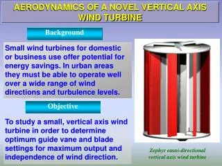
VAWT : Current Trends • VAWT design have been always mistreated by literature and market. • The peculiarity of VAWT turbines to operate was the major problem. • VAWT can have a very important advantage in the actual market. • Deeper analysis of energy production by VAWTs showed that, they are best suited for certain conditions of wind, like turbulence, gusts or fluctuations. • The technology of the vertical axis can perform better than the usual horizontal axis one.
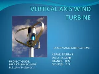
Types of Vertical Axis wind Turbines • Savonius • Darrieus • Cycloturbine • Giromill
General Configuration of a DarrieustypeVertical-Axis Wind Turbine
Troposkein • The troposkein is the curve an idealized rope assumes when anchored at its ends and spun around its long axis at a constant angular velocity. • This shape is similar to the shape assumed by a skipping rope. • The shape is independent of rotational speed in the absence of gravity. • The troposkein does not have a closed-form representation; in the absence of gravity. • However, the shape varies with respect to rotational speed in the presence of gravity.
The Shape Equation for Troposkein • The form of a troposkein can be approximated for a given gravitational acceleration, rope density and angular velocity by iterative approximation. • This shape is also useful for decreasing the stress experienced by the blades of a Darrieus vertical axis wind turbine. • The Darrieus wind turbine with a troposkien shaped blades has advantage of working under the effect of high centrifugal forces without failure.
The Turbine Rotor Subsystem : VAWT • Blades are shaped to approximate a troposkien
Design Models for VAWT • Several design models are developed for accurate analysis of VAWT. • The most complex model is vortex Model. • The complex structure of the resulting vortex system applicable to the Darrieus Turbine configuration, the computer time required is excessive. • The simplest model is a single stream tube Model. • In SST model, the forces on the airfoil blades are computed, using this uniform velocity across the turbine rotor upstream. • SST model is elegant in its simplicity and predicts overall performance rather well for lightly loaded blades.
Single Stream Tube (SST) Model V V Vw
R
Single Stream Tube (SST) Model V V • VAWT blades project a cylinder that is parallel to the stream tube. • The blades cross the normal actuator disc twice along their upwind and downwind path. Vw azimuth angle The axial induction factor:
Local Instantaneous Velocities The relative velocity component (VR) Normalized relative velocity
Kinetics Vs Kinematics of VWAT Normalized relative velocity angle of attack Normal Force Coefficient Tangential Force Coefficient
Local Instantaneous Torque per Blade The local instantaneous Tangential force (dFti) on one single airfoil at certain θ is The local instantaneous Torque (di) on one single airfoil at certain θ is A single blade passes each stream tube twice per revolution in the upstream and downsteam.
Time Averaged Local Torque The time averaged local torque generated by “B” blades and twice per revolution can be expressed as The time averaged total torque generated by “B” blades and twice per revolution can be expressed as
Failure of SST Model • SST Mode is incapable of handling wind velocity variations across the rotor. • These variations become increasingly large at higher blade solidities and blade tip speeds. • However, SST can incorporate wind shear effects.
Simple & Sophisticated Model • A somewhat more sophisticated model than the single stream tube model is one in which a series of stream tubes are assumed to pass through the rotor. • The same basic principles which were applied to each of the multiple stream tubes. • The multiple stream tube model gives rise to a velocity distribution through the rotor which is a function of the two spatial coordinates perpendicular to the stream wise direction. • The multiple stream tube model does predict overall performance very well. • This model yields a more realistic distribution of blade forces, and can easily be modified to include wind shear effects.
Simplified Geometry of stream tubes in the plane of rotation • The swept area is discretized into a mesh by dividing the straight blades into segments and separating the incident wind into independent stream tubes. • Figure illustrates the independent straight stream tubes for a choice of 16 azimuthal positions
The Double Multiple Stream tube Analysis • The Double Multiple Stream tube (DMST) Method recognizes the difference between the upwind and downwind passes of each blade by dividing each stream tube into an upwind half and a downwind half . • The turbine’s interaction with the wind in the upwind and downwind passes of the blades is accounted separately. • The assumption is made that the wake from the upwind pass is fully expanded and the ultimate wake velocity has been reached before the interaction with the blades in the downwind pass. • The downwind blades therefore see a reduced ‘free-stream’ velocity. • This approach more accurately represents the variation in flow through the VAW turbine.