Download
1 / 5
50 likes | 74 Vues
This paper presents the design and implementation of a triangular loop antenna using aluminum tubing of diameter 10mm with high electrical conductivity and reflecting ability. The antenna operates in very high frequency VHF band covering a frequency range of 140 to 150MHz. It has a gain of 3 dB and a radius of coverage of about 100 kilometers. It was constructed as a prototype antenna and tested at the author home base QTH with grid locator of PK23CO, where signals from DW4PGS, DW4PLN, DW4GSV, and DV4RBC were received with sharp audible sound Q5 and full signal strength S9 . Better receptions were recorded for PD03, KB912 19, and KB951 -B157 on days with good propagation. Measurement result shows that the proposed antenna can work properly and meet well to be used in as reliable low cost homebrew effective VHF wide band antenna and it is an omnidirectional antenna. Dexter M. Toyado "Design and Implementation of A VHF Tri-Loop Antenna for 2-Meter Amateur Band" Published in International Journal of Trend in Scientific Research and Development (ijtsrd), ISSN: 2456-6470, Volume-3 | Issue-6 , October 2019, URL: https://www.ijtsrd.com/papers/ijtsrd28120.pdf Paper URL: https://www.ijtsrd.com/engineering/electronics-and-communication-engineering/28120/design-and-implementation-of-a-vhf-tri-loop-antenna-for-2-meter-amateur-band/dexter-m-toyado<br>

E N D
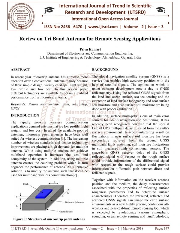
International Journal of Trend in Scientific Research and Development (IJTSRD) Volume 3 Issue 6, October 2019 Available Online: www.ijtsrd.com e-ISSN: 2456 – 6470 Design and Implementation of A VHF Tri-Loop Antenna for 2-Meter Amateur Band Dexter M. Toyado DU4DXT, CE, MM, Catanduanes State University, Virac, Catanduanes, Philippines ABSTRACT This paper presents the design and implementation of a triangular loop antenna using aluminum tubing of diameter 10mm with high electrical conductivity and reflecting ability. The antenna operates in very high frequency (VHF) band covering a frequency range of 140 to 150MHz. It has a gain of 3 dB and a radius of coverage of about 100 kilometers. It was constructed as a prototype antenna and tested at the author home base (QTH) with grid locator of PK23CO, where signals from DW4PGS, DW4PLN, DW4GSV, and DV4RBC were received with sharp audible sound(Q5) and full signal strength(S9). Better receptions were recorded for PD03, KB912-19, and KB951 –B157 on days with good propagation. Measurement result shows that the proposed antenna can work properly and meet well to be used in as reliable low cost homebrew effective VHF wide band antenna and it is an omnidirectional antenna. KEYWORDS: VHF Communication, Radio Waves, Triangular Loop How to cite this paper: Dexter M. Toyado "Design and Implementation of A VHF Tri- Loop Antenna for 2-Meter Amateur Band" Published in International Journal of Trend in Scientific Research and Development (ijtsrd), ISSN: 2456- 6470, Volume-3 | Issue-6, October 2019, pp.481-485, https://www.ijtsrd.com/papers/ijtsrd28 120.pdf Copyright © 2019 by author(s) and International Journal of Trend in Scientific Research and Development Journal. This is an Open Access article distributed under the terms of the Creative Commons Attribution License (CC (http://creativecommons.org/licenses/by /4.0) IJTSRD28120 URL: BY 4.0) INTRODUCTION Communication is connecting people. It enables humans to share ideas and experiences indirectly or vicariously fostering interpersonal bond. Communication is the main reason why the earth keeps on moving forward. Radio communication sends signals by radio to communicate with other. From Audio, Telephony, Television, Satellite, Navigation, and the advance used of Radio communication signals in Radar Technology, Data (Digital Radio), Amateur Radio.In todays world, radio communication is widely used. Without radio communication we maybe still are living in last century. Radio systems used for communications have the following elements. With more than century of development, from the time of Marconi to present. The communication system process is implemented by a wide range of methods and been specialized for different communications system. Each system contains a transmitter. A transmitter consists of a source of electrical energy, producing an alternating current (AC) of a desired frequency of oscillation. The transmitter contains a system to modulate (change) some property of the energy produced to impress a signal on it. The transmitter sends the modulated electrical energy to a tuned resonant antenna. The resonant antenna structure for transmit converts the rapidly changing alternating current into an electromagnetic wave that can move through free space. The electromagnetic wave is intercepted by a tuned receiving antenna. The resonant antenna structure for receiving captures some of the energy of the wave and returns it to the form of oscillating electrical currents. At the receiver, these currents are demodulated, which is converted to a usable signal form. Frequency modulation varies the frequency of the carrier. The instantaneous frequency of the carrier is directly proportional to the instantaneous value of the input signal. Digital data can be sent by shifting the carrier's frequency among a set of discrete values, a technique known as frequency-shift keying. Frequency Modulation (FM) is commonly used at VHF radio fidelity broadcasts of music and speech . Normal (analog) TV sound is also broadcast using FM. Antenna An antenna is an electrical device which converts electric currents into radio waves, and vice versa. It is usually used with a radio transmitter or radio receiver. In transmission, a radio transmitter applies frequency electric current to the antenna's terminals, and the antenna radiates the energy from the current as electromagnetic waves (radio waves). In reception, an antenna intercepts some of the power of an electromagnetic wave in order to produce a tiny voltage at its terminals, that is applied to a receiver to be amplified. An antenna can be used for both transmitting and receiving (ARRL, 1999) frequencies for high- an oscillating radio @ IJTSRD | Unique Paper ID – IJTSRD28120 | Volume – 3 | Issue – 6 | September - October 2019 Page 481
International Journal of Trend in Scientific Research and Development (IJTSRD) @ www.ijtsrd.com eISSN: 2456-6470 The Loop Antenna A loop antenna is an antenna consisting of loop of electrical conductor such as wires, tubing, or solid metals. Its end is connected to a balanced transmission line. For this design, the used of resonant loop antenna is utilize where the length of the loop is approximately equal to the wavelength. Self- resonant is typically used for VHF and UHF. Compared to the dipole or folded dipole, it transmit less towards the sky or ground, giving it somewhat higher in gain in the horizontal direction. The use of a triangular loop rather than the conventional circular or quad is utilized since there is no recorded article or known experiment regarding the exploration of a triangular loop antenna for VHF band. Most loop antenna is in a form of a Delta Loop is design for HF band. Also this study will further evolve in the design of a collinear triangular loop. The triangular loop is shape as triangle with its apex at the top and two edge corners at the bottom where the feed line is attaché d to one of its corner. Design Consideration To design this tri-loop antenna, using aluminum tubing of diameter 10mm was chosen and used to make the elements. This choice was made for that it is the most common type of antenna element in the area and high electrical conductivity and also resistance to corrosion. The length of the tri-loop was determined based on a frequency of 145.00mhz (center frequency for amateur band in the Philippines). Using the modified formula of finding the length of the loop develop by L.B. Cebik, L = 1065/f(mhz) for VHF frequency Where: L= length of the loop 1065 = is a constant used in the design of most commonly loops such as circular and quad F = frequency in megahertz. From the given formula the result dimension of the loop is L=1065/145mhz = 7.35 feet. Since this is a tri-loop, the dimension of each side is 2.24ft. The full dimension is shown in the figure below. The Materials used for building and implementation of the project. Quantity 1pc – 8ft. 12 mm Aluminum Tubing 1pc – ½”x2”x4’ 1pc Plastic connector bended 60 deg. 2 pcs – 10mm dia. 4pcs -1/4” 1 pc - 2-3” dia. 6 pcs 1 sachet Waterproofing sealant 1 roll Analysis of the Performance Using 4NEC2 software to simulate the radiation pattern and other performance criteria of the antenna. The dimension use for this simulation is the dimension from the results using the formula of the general HF loop antenna. The result gives an outstanding 3 dB. Materials Good Lumber Hose clamp Metal screw U-clamp Plastic straps Coaxial Cable Figure2. The 4NEC2 software analysis of the antenna Optimize performance of the antenna To optimize the performance of the quad loop, I use 4NEC2 optimization program to get the maximum performance of the antenna by changing the dimension of the width of the system. Figure1. Diagram of the Tri-loop antenna @ IJTSRD | Unique Paper ID – IJTSRD28120 | Volume – 3 | Issue – 6 | September - October 2019 Page 482
International Journal of Trend in Scientific Research and Development (IJTSRD) @ www.ijtsrd.com eISSN: 2456-6470 Figure4. Actual Completed Antenna Testing Procedure and Results 1.Antenna Analyzer The antenna is tested first by getting the SWR reading to get the optimized performance in terms of receive and transmit capability. The SWR reading of the antenna was then tested using MFJ Antenna Analyzer. The result gives a promising and positive data. Figure3. The result gives us 3dB and Efficiency of 100%. Implementation Procedure The antenna was constructed using aluminum tubing with a 12mm diameter for the element, 1/2” x 2” x 4’ wooden holder, 2” diameter GI pipe as boom, hacksaw for cutting the materials, gimlet for drilling holes, screw nails for fastening the elements to the boom, measuring tape, 50-ohm coaxial cable as transmission line and feeders to house the terminals. The elements were first measured, bend using pipe bender and cut out of the aluminum rail and holes drilled at their holder location. The holder is then fitted with u-clamp for the attachment to the mast. The two endpoint of the elements is then attached and connected by a plastic connector (or a coaxial inner core) The feeder lines were fixed to the element on one of the lower corner of the triloop with hose clamp. The hose clamp will enable the installer to adjust the SWR reading by simply moving in and out the clamp on the element from the corner endpoints. With the feeders in place, cover the connection of the feeder with water proofing sealant as not to introduce corrosion and rust in the connector. Finally, the coaxial cable from the feed point is connected to a VHF Transmitter Radio. Figure5. Using the MFJ Antenna Analyzer to test the antenna for SWR and Impedance @ IJTSRD | Unique Paper ID – IJTSRD28120 | Volume – 3 | Issue – 6 | September - October 2019 Page 483
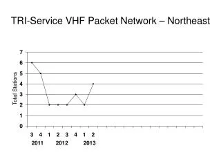
International Journal of Trend in Scientific Research and Development (IJTSRD) @ www.ijtsrd.com eISSN: 2456-6470 2.Actual Transmission (TX/RX) The second method is to test the antenna by transmitting. The antenna is then connected to a Transmitting radio set using Icom 2200H with an output power of 65Watts. The radio is connected to the antenna by coaxial cable with impedance of 50 Ohms. The testing covers all the VHF radio frequency band and focused on 136.000 – 160.00Mhz. The result is shown below with the actual testing of the antenna unit. Figure6. Actual SWR reading with Diamond SX-200 Meter Using an Icom 2200H with 65 watts of output power in an amateur frequency. VSWR Readings 1.8 1.6 1.4 1.2 VSWR 1 0.8 0.6 0.4 0.2 0 136.000 138.000 140.000 142.000 143.000 144.000 145.000 146.000 147.000 148.000 149.000 150.000 152.000 153.000 154.000 Figure7. The VSWR reading on corresponding VHF Frequency 3.Signal Check for Strength and Clarity of the transmission. The audio quality and the signal strength were then tested with conversation with other radio operation from different location. The antenna is installed at DW4DXT QTH or home base with grid locator PK23CO. Below shows the table of the strength reading and quality of audio from different operator and different locations. Table1. Signal strength and audio quality of transmission Operator(s) Station DW4PGS (Fixed Station) Virac, Catanduanes Frequency (Mhz) 145.580 Distance (KM) 3 Audio Quality Q5 Signal Strength S9 Grid Locator/ Location DW4PLN (Fixed Station) San Andres, Catanduanes 145.580 12 Q5 S9 DY4TMD (Mobile) Bato, Catanduanes 146.880 10 Q5 S9 DW4GSV (Fixed Station) Cagraray Island, Albay 145.580 45 Q5 S5 KB951 –B157 (Fixed Station) Tabaco City 146.020 58 Q5 S3 DY4MDJ (Fixed Station) Malilipot, Albay 145.460 58 Q5 S5 DV4RBC (Fixed Station) Sto Domingo, Albay 144.160 60 Q5 S9 Hotel Kilo (Fixed Station) Naga City 145.580 105 Q1 Busy/DS PD03 (Fixed Station) Goa, Camarines Sur 146.870 80 Q3 Busy MAM (Fixed Station) Tigaon, Camarines Sur 145.580 78 Q5 S1 KB912-19 (Fixed Station) Magallanes, Sorsogon 146.170 93 Q2 Busy @ IJTSRD | Unique Paper ID – IJTSRD28120 | Volume – 3 | Issue – 6 | September - October 2019 Page 484
International Journal of Trend in Scientific Research and Development (IJTSRD) @ www.ijtsrd.com eISSN: 2456-6470 Goa, Camarines Sur Tigaon, Camarines Sur Naga City Tabaco City Cagraray Island, Albay Sto. Domingo, Albay Legazpi City Magallanes Sorsogon Figure8. Ranges of transmission of the antenna CONCLUSION Results of tests have shown that the tri-loop antenna is wideband in operation covering frequency in VHF bands. It is reliable and effective for transmitting radio signal when properly design and constructed. The antenna is cheap to construct and uses materials that are locally available and even use materials from scrap aluminum from junkshops. It serves as a good substitute to commercially available antenna for both amateur and commercial use. The antenna performs as an omnidirectional antenna. Acknowledgements I am very deeply grateful to the software develop by G. J. Burke and A. J. Poggio of Lawrence Livermore Laboratory. Fr. Stephen Polo for the MFJ Antenna Analyzer and the ideas to homebrew amateur antenna. To my wife and kids for supporting me in my hobby of homebrewing amateur radio devices and antenna. REFERENCES [1]American Relay League. ARRL Antenna Book, 13th Edition, ARRL Inc. Connecticut. 1999 [2]Balanis, C. A. Antenna Theory – Analysis and Design, 2nd Edition, John Wiley and Sons, Inc. New York, 1997. P 941. [3]Band, Y. B. Light and Matter, 1st Edition, John Wiley Inc. England.2006. P 640 [4]Kennedy, G. and Davis, B. Electronic Communication Systems. 4th Edition. Tata McGraw-Hill Publishing Company Ltd. New Delhi. 1993, P 763. [5]Puri, R. K. and Babbar, V. K. Solid State Physics and Electronics. 4th Edition, Academic Publishers. India. 2007. [6]Roddy, D. and Coolen. Electronic Communication. 4th Edition, Prentice-Hall Inc. New York.1997. P 820. [7]Steve, A. and Allday, J. Advanced Physics. 1st Edition, Oxford University Press. London. 2000. P 639. [8]Word/Mac WDBN version 0.92 of NEC-2 User’s Guide from <http://www.traveller.com/~richesop/nec/> @ IJTSRD | Unique Paper ID – IJTSRD28120 | Volume – 3 | Issue – 6 | September - October 2019 Page 485