Download
1 / 29
290 likes | 302 Vues
In this project we present the Accessible GSM Based Embedded Medical Critical Care Signal Monitoring System. This device has been designed to be accessible for clients of different abilities and ages. The Accessible GSM based Medical Critical Care Signal Monitoring System that we have designed measures blood pressure, blood oxygen saturation, heart rate, temperature and respiration rate using non invasive technique and takes step wise measures in extreme conditions. In this system, these vital signs are displayed on a monitor and sent to a computer via Bluetooth as well as send these data to patents relatives mobile number as well as cross ponding Doctors, Nurses mobile number for immediate assistance via GSM based SMS technique and through a secure website that is part of the system, the patents and their relatives can upload their vital signs via any Internet connected computer. This allows clients to communicate their health status to physicians and healthcare providers anywhere in the world. Accessibility is provided through a large, well lit LCD screen, a speaker Alarm system, and Braille customized buttons. Vital signs are displayed on the large LCD screen, as well as alarmed through a speaker system in extreme situations. A simple 3 button design provides an easy to use user interface, appropriate for all age levels and technological savvy. Also, all buttons are customized with Braille or Universal Symbols for the vision impaired. The monitor includes solar rechargeable back up batteries in case of power failure, or if the client just does not to be homebound by their health monitoring needs. The implementation of the project includes various hardware components as well as software. Prince Kumar Singh | Akash Kundu | Sumit Kumar Jaiswal "GSM Based Embedded Medical Critical Care Signal Monitoring System" Published in International Journal of Trend in Scientific Research and Development (ijtsrd), ISSN: 2456-6470, Volume-3 | Issue-4 , June 2019, URL: https://www.ijtsrd.com/papers/ijtsrd25126.pdf Paper URL: https://www.ijtsrd.com/engineering/electronics-and-communication-engineering/25126/gsm-based-embedded-medical-critical-care-signal-monitoring-system/prince-kumar-singh<br>

E N D
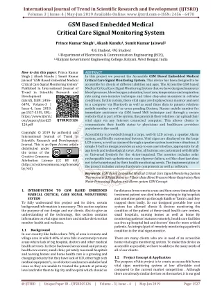
International Journal of Trend in Scientific Research and Development (IJTSRD) Volume: 3 | Issue: 4 | May-Jun 2019 Available Online: www.ijtsrd.com e-ISSN: 2456 - 6470 GSM Based Embedded Medical Critical Care Signal Monitoring System Prince Kumar Singh1, Akash Kundu1, Sumit Kumar Jaiswal2 1UG Student, 2PG Student 1,2Department of Electronics & Communication Engineering (ECE), 1,2Kalyani Government Engineering College, Kalyani, West Bengal, India How to cite this paper: Prince Kumar Singh | Akash Kundu | Sumit Kumar Jaiswal "GSM Based Embedded Medical Critical Care Signal Monitoring System" Published in International Journal of Trend in Scientific Research and Development (ijtsrd), ISSN: 2456- 6470, Volume-3 | Issue-4, June 2019, pp.1527-1555, URL: https://www.ijtsrd.c om/papers/ijtsrd25 126.pdf Copyright © 2019 by author(s) and International Journal of Trend in Scientific Research and Development Journal. This is an Open Access article distributed under the terms of the Creative Commons Attribution License (CC BY 4.0) (http://creativecommons.org/licenses/ by/4.0) 1.INTRODUCTION TO GSM BASED EMBEDDED MADICAL CRITICAL CARE SIGNAL MONATORING SYSTEM To fully understand this project and its drive, certain background information is necessary. This section explains the purpose of our design and our clients. Also to give an understanding of the technology, this section contains information on vital signs monitors and similar devices that monitor health and wellness. ABSTRACT In this project we present the Accessible GSM Based Embedded Medical Critical Care Signal Monitoring System. This device has been designed to be accessible for clients of different abilities and ages. The Accessible GSM based Medical Critical Care Signal Monitoring System that we have designed measures blood pressure, blood oxygen saturation, heart rate, temperature and respiration rate using non-invasive technique and takes step-wise measures in extreme conditions. In this system, these vital signs are displayed on a monitor and sent to a computer via Bluetooth as well as send these data to patents relatives mobile number as well as cross ponding Doctors, Nurses mobile number for immediate assistance via GSM based SMS technique and through a secure website that is part of the system, the patents & their relatives can upload their vital signs via any Internet connected computer. This allows clients to communicate their health status to physicians and healthcare providers anywhere in the world. Accessibility is provided through a large, well-lit LCD screen, a speaker Alarm system, and Braille customized buttons. Vital signs are displayed on the large LCD screen, as well as alarmed through a speaker system in extreme situations. A simple 3-button design provides an easy-to-use user interface, appropriate for all age levels and technological savvy. Also, all buttons are customized with Braille or Universal Symbols for the vision-impaired. The monitor includes solar rechargeable back-up batteries in case of power-failure, or if the client just does not to be homebound by their health monitoring needs. The implementation of the project includes various hardware components as well as software. Keywords: GSM Based Embedded Medical Critical Care Signal Monitoring System Thermometer 3 Pulse Oximeter 7 Heart Rate Blood Pressure Meter Respiratory Rate Meter Processing, Display, and Alarm system GSM Concept IJTSRD25126 far distance from remote areas and then some times delay in treatment patient was died before reaching to big hospitals and sometime patents go through Baidh or Tantric and they trapped them badly. So our designed portable low cost system has allowed clients & doctors monitoring the condition of the patient at these small health care centers, small hospitals, nursing homes as well as home By monitoring patients’ statuses remotely, health care facilities can free up hospital bad and doctors’ time for more critical patients. An integral part of remotely monitoring a patient’s condition is the vital signs monitor. 1.1 In our country like India where 70% of area is remote and village area in which 40% of area falls in extremely remote areas where lack of big hospital, doctors and other medical health services. In these backward areas small and primary health care center, small clinic, privately run small hospitals and nursing homes and home health care is a growing and changing industry but they have lack of ICU, other high tech medical equipment’s, no of doctors and nurses and also fund issue so they are unable to treated the patents at primary level and refer them to big city and hospital which should so Background There are many clients who are in need of an accessible home vital signs monitoring system. To make this device as accessible as possible, we have to address the many needs of all of our clients. 1.2 The purpose of this project is to create an accessible home vital signs monitoring system at low affordable cost compared to the current market competition . Although there are already similar devices on the market, it is our goal Project Concept & Application @ IJTSRD | Unique Paper ID – IJTSRD25126 | Volume – 3 | Issue – 4 | May-Jun 2019 Page: 1527
International Journal of Trend in Scientific Research and Development (IJTSRD) @ www.ijtsrd.com eISSN: 2456-6470 to design a monitoring system that meets our clients’ specific needs. This device will improve our clients’ quality of life by allowing health care professionals to monitor them from home, rather than from a bed in a hospital or nursing home. Our clients can maintain their health, and not appear sick to their friends, and continue to live with their families. The device we design will allow them to do these things. It will be accessible to the vision and hearing impaired, and it will be cost effective. Most systems available today are very expensive, and our purpose is to make an affordable device that is also accessible and easy to use. 1.3 The remainder of the final report covers design, budget, and other engineering considerations. The next section details the design process by discussing the three alternative designs and the optimal design of the accessible home vital signs monitoring system. The alternative designs show the changes that our vital signs monitoring system went through on its way to the final design, the optimal design. Following this section are the realistic constraints, safety issues, and impact of engineering solutions. The realistic constraints and safety issues were factors that had to be kept in mind when designing our device. The impact of engineering solutions section describes how our design affects different areas in society, including the environment, the economy, and the global stage. Next discussed is life-long learning and how our device and its design has contributed to our life-long learning. The report concludes with our budget and each team member’s contribution to the report and design of the device. Acknowledgements, references, and an appendix containing updated device specifications are also included. Map for the Rest of the Report Our accessible home vital signs monitoring system will have the capability to non-invasively gather the client’s heart rate, blood pressure, blood oxygen saturation level, and body temperature, and then send these data to their healthcare provider. The data will be sent via GSM based SMS service to patient’s relatives, Doctors, nurses and data also via wireless means to a password-protected, encrypted website. This accessible home vital signs monitoring system design is an accurate and consistent way to obtain a patient’s vital signs, regardless of the caregiver’s skill level. The buttons on the front panel of the monitor will be large and printed that can be easily understood, allowing patients who are vision- impaired to successfully operate the monitor. Also to accommodate vision-impaired clients, a text-to-speech function will be implemented to allow the monitor to audibly communicate current vital signs readings. In addition, four bright LCD screens with wide viewing angles will be used to display the patients’ vital signs. A visual and audio alarm will be installed to alert clients if their vital signs are abnormal. To collect the data, medical transducers will be commercially purchased and integrated into the accessible vital signs monitoring system. The items to be purchased are a finger pulse oximeter probe, an oral temperature probe, and an automatic blood pressure cuff. 2.Project Design & Development Engineering design is a process that involves research and revision. The entire project divided into five circuit blocks created for our accessible GSM based Embedded Medical Critical Care Signal Monitoring System and the optimal design that was chosen. One circuit block design for Thermometer (Non Invasive), second one is Pulse Oximeter & heart rate (Non Invasive), third one is Blood Pressure Meter (Non Invasive), fourth one is Respiratory Rate Meter (Non Invasive) and fifth one is computing, processing, GSM & alarm unit. In each design section, any changes made are discussed, followed by an explanation of each subunit of the design. The optimal design was chosen because it keeps costs down while still being an effective home vital signs monitoring system. It is also the design that is safest, will last the longest, and be the easiest to manufacture. 2.1 Block Diagram of the purposed project Fig.1 GSM BASED EMBEDDED MADICAL CRITICAL CARE SIGNAL MONATORING SYSTEM @ IJTSRD | Unique Paper ID – IJTSRD25126 | Volume – 3 | Issue – 4 | May-Jun 2019 Page: 1528
International Journal of Trend in Scientific Research and Development (IJTSRD) @ www.ijtsrd.com eISSN: 2456-6470 2.1.1 2.1.2 Theory- To measure body temperature, a thermistor circuit will be used. The thermistor will be in the form of a commercially purchased. It will convert changes in temperature to changes in voltage. Thermistors are inherently nonlinear, so to linearize the output of the thermistor, it will be placed in series with a resistor . The value of the resistor will be determined from the resistance of the thermistor at room temperature and data from the temperature probe spec. sheet. For our use as an oral temperature probe, the thermistor needs to be linearized for temperatures from 90-104° F (32-40°C). After being Circuit Diagram- Description of Individual Block Thermometer linearized, the signal will be sent to a low-pass filter to filter out any noise and then passed to a non-inverting amplifier to be amplified. Finally, the signal will be sent to the microprocessor where it will be analyzed and passed to a LCD screen to be displayed. The thermometer will be tested by placing the probe in a beaker of water heated to a certain temperature and comparing the resulting temperature given by the thermometer to the actual temperature of the water. Final testing will be done by taking group members’ temperature with the thermometer and comparing the reading with that taken by a commercial digital thermometer. Fig.2 Circuit diagram of Digital Thermometer Circuit Description Circuit Description Here we use the DS18B20 RTD thermistor witch is converts changes in temperature to changes in voltage. Unfortunately, thermistors are inherently non-linear. The Steinhart-Hart equation describes the resistance-temperature curve of a thermistor 1/T= a+b ln(R) + c ln3 (R) where T is the temperature in kelvins, R is the resistance in ohms, and a, b, and c are constants called the Steinhart-Hart parameters which are usually provided by the thermistor manufacturer .The internal construction of the thermistor described in figured below. This output can be linearized over a small range of temperatures through the use of a Wheatstone bridge Thus, the resistance of the thermistor, RT1, can be modeled by the first order equation where R is the resistance of the other resistance in the Wheatstone bridge, α is the temperature coefficient, and T is the change in temperature from the reference temperature ( T=T-To) in degrees Kelvin. The reference temperature (To) of the thermistor is given by the manufacturer and for medical thermistors it is usually around 300°K. The temperature coefficient, α, can be calculated from the following equation: @ IJTSRD | Unique Paper ID – IJTSRD25126 | Volume – 3 | Issue – 4 | May-Jun 2019 Page: 1529
International Journal of Trend in Scientific Research and Development (IJTSRD) @ www.ijtsrd.com eISSN: 2456-6470 where β is a temperature constant, typically around 4000°K [10]. The value of the resistors, R, used to linearize the thermistor will be determined from the reference temperature and other values given by the manufacturer (β or α) using the above equations. For our use as an oral temperature probe, the thermistor needs to be linearized (calibrated) around 98.6° F (37°C), for a temperature range of at least 90-104° F (32-40°C). When linearizing the thermistor, we must be careful to keep the accuracy of the thermometer high (+ .1°C) so as to be able to take appropriate measurements. After being linearized, the signal is sent to a3rd order Butterworth low-pass filter to remove any noise. The cutoff frequency for the filter is about 60Hz to remove any noise from room lights and other sources (fc = 1/2πR2C) Component Uses Compnent Specification Quantity OP-amp OP-amp Resistance Resistance Resistance Resistance Resistance Capacitor 0.22uf(223) Capacitor Temperature sensor Component Data sheet DS18B20 Temperature Sensor – DS18B20 is a 3pin RTD thermistor waterproof metalshielded temperature sensor. It Measures temperatures from -55°C to +125°C (-67°F to +257°F) ±0.5°C accuracy. Its power supply range is 3.0V to 5.5V and Converts temperature to 12-bit digital word in 750ms (max.) Pin Diagram: LM307 Operational Amplifiers-The LM307 series are complete, general purpose operational amplifiers, with the necessary frequency compensation built into the chip. Advanced processing techniques make the input currents a factor of ten lower than industry standards like the 709. Yet, they are a direct, plug-in replacement for the 709, LM101A and 741. The LM307 series offers the features of the LM101A, which makes its application nearly foolproof. In addition, the deviceprovides better accuracy and lower noise in high impedance circuitry. The low input currents also make it particularly well suited for long interval integrators or timers, sample and hold circuits and low frequency waveform generators. Further, replacing circuits where matched transistor pairs buffer the inputs of conventionalIC op amps, it can give lower offset voltage and drift at a lower cost. The LM307 is guaranteed over temperature range of from 0°C to a70°C. LM307 LM324 470k 15k 10k 4.6k 1k 1 2 4 1 1 1 3 2 1 1 Features ?Offset voltage 3 mV maximum over temperature ?Input current 100 nA maximum over temperature ?Offset current 20 nA maximum over temperature ?Guaranteed drift characteristics Absolute Maximum Ratings- Supply Voltage- Power Dissipation (Note 1)- Differential Input Voltage- Input Voltage (Note 2)- Output Short Circuit Duration- Operating Temperature Range (TA)- 0°C to a70°C. Pin Diagram- 1uf(105) DS18B20 LM307 ± 12v to 18V 500 mW ±30V ± 12v to 18V Continuous LM324 Operational Amplifiers- The LM324 series op-amp consists of fourindependent, high-gain, internally frequency- compensated operational amplifiers designed specifically to operate from a single power supply over a wide range of voltages. In the linear mode, the input common-mode voltage range includes ground and the output voltage can also swing to ground, even though operated from only a single power supply voltage. The unity gain crossover frequency and the input bias current are temperature- compensated. Fig.3 DS18B20 Temerature senser Pin Description: Pin No 1 Supply voltage; 5V (+35V to -2V) 2 Output voltage (+6V to -1V) 3 Ground (0V) Function Name Vcc Output Ground @ IJTSRD | Unique Paper ID – IJTSRD25126 | Volume – 3 | Issue – 4 | May-Jun 2019 Page: 1530
International Journal of Trend in Scientific Research and Development (IJTSRD) @ www.ijtsrd.com eISSN: 2456-6470 FEATURES ?Internally frequency-compensated for unity gain ?Large DC voltage gain: 100dB ?Wide bandwidth (unity gain): 1MHz (temperature- compensated) ?Wide power supply range Single supply: 3VDC to 30VDC or dual supplies: ±1.5VDC to ±15VDC ?Very low supply current drain: essentially independent of supply voltage (1mW/op amp at +5VDC) ?Low input biasing current: 45nADC (temperature- compensated) ?Low input offset voltage: 2mVDC and offset current: 5nADC ?Differential input voltage range equal to the power supply voltage ?Large output voltage: 0VDC to VCC-1.5VDC swing @ IJTSRD | Unique Paper ID – IJTSRD25126 | Volume – 3 | Issue – 4 | May-Jun 2019 Page: 1531
International Journal of Trend in Scientific Research and Development (IJTSRD) @ www.ijtsrd.com eISSN: 2456-6470 2.1.3 Pulse Oximeter & Heart Rate Theory- Pulse oximetry is a non-invasive method that allows the monitoring of oxygen saturation of a patient’s hemoglobin (Hb). The hemoglobin is a protein which is present in the red cells of the blood and it is responsible for the oxygen (O2) transport throughout the body. There are two forms of hemoglobin in blood: oxygenated hemoglobin (HbO2) and deoxygenated hemoglobin (Hb). Hb combines with the oxygen to form HbO2 in the lungs through a loading reaction, The HbO2 is transported to the tissues capillaries where it dissociates to yield Hb and free O2 molecules through an unloading reaction, and oxygen is used in mitochondria. The absorption of light by hemoglobin varies according the saturation in oxygen. When the hemoglobin without oxygen bond with the oxygen to form oxygenated hemoglobin, it becomes red; in the dissociation of oxygen hemoglobin gets darker. This difference of colours is because Hb and HbO2 have also a difference in the optical spectral in the range of wavelengths between 600nm (close to red) and1000nm (near infrared). Figure 5: Transmittance oximetry v/s Reflectance oximetry Here, the transmitted light is detected by the photo diode, and is found to have higher signal to noise ratio. So we chose for our project transmittance oximetry. Figure 6: Emission of Red and Infrared LED on the light detector via the finger/tissue The output of the photodiode is very less in amplitude, and also very noisy. Before giving to the microcontroller, high amplification and filtering is required to get the desired signal. Two band pass filters are used for the signal processing. The microcontroller is required to perform the analog to digital conversion of the signal, and calculate the peak amplitudes of the signal to generate the heart rate and SpO2. The values are displayed on a 16*2 alphanumeric LCD. Background Math: The ratio of the absorbance due to red led to that of infrared led can beformulated as: R = ((Vmax(Red) Vmin(Red)) / Vmin(Red)) / (Vmax(Infrared) Vmin(Infrared)) / Vmin(Infrared) And oxygen saturation of blood can be formulated as: SpO2=HbO2/(HbO2+Hb) x 100%. Heart Rate - Pulse oximetry will also be used to determine heart rate, as in Design 1. There are pulsatile signals detected in the intensity of the detected light by the photodiode. One pulse is one cardiac cycle. The microprocessor will count the pulses to determine heart rate (beats per minute), which will be displayed on an LCD screen. Figure 4: Absorption of HBO2 and HB at different wavelength As it is possible to see in Figure 4, oxygenated and deoxygenated hemoglobin have a significantly different optical spectra in the wavelength range from 600nm to 1000nm.The difference is big in some wavelengths (around 660nm in the red region and around 910nm in the infrared region) and small or not existing in other ones (isopiestic wavelength). The difference in these two wavelengths can be used to calculate the oxygen saturation in blood. Pulse Oximetry can be done using two methods, reflectance oximetry and transmittance oximetry. In case of reflectance oximetry, the two LEDs and the photodiode are on the same side. Here, the light moves through the skin, muscle and blood vessel, and is reflected back from the bone. Reflectance oximetry has low signal to noise ratio and difficult to set up. In case of transmittance oximetry, the two LEDs and the photodiode are on the opposite side of the finger. @ IJTSRD | Unique Paper ID – IJTSRD25126 | Volume – 3 | Issue – 4 | May-Jun 2019 Page: 1532
International Journal of Trend in Scientific Research and Development (IJTSRD) @ www.ijtsrd.com eISSN: 2456-6470 Block Diagram- Fig.6 Block Diagram of Pulse Oximeter Circuit Diagram- Fig.7 Circuit Diagram of Pulse Oximeter Circuit Description- The hardware for this project consisted of a light source and a photo detector. The light is shown through the tissue on the finger. As the blood passes through capillaries in the finger, the variation in blood volume causes a variation in the light detected by the phototransistor. The source and detector are mounted on either side of the finger to measure changes in transmitted light. In the project, we used an infrared LED and Red LED. The ratio of these two absorptions will give us a Sp02 reading. The measurement starts @ IJTSRD | Unique Paper ID – IJTSRD25126 | Volume – 3 | Issue – 4 | May-Jun 2019 Page: 1533
International Journal of Trend in Scientific Research and Development (IJTSRD) @ www.ijtsrd.com eISSN: 2456-6470 when the MCU generates a PWM signal that varies the LED intensity. LED calibration is performed by taking the LED filtered baseline and using an algorithm described in the Software model which changes the PWM duty cycle value to adjust the LED intensity for every kind of user. The LED driver circuit helps to drive LEDs so that power is not provided directly by the MCU. Using transistors, the LEDs are powered directly by the VCC line and controlled by the MCU. The switch control pin on the MCU selects which LED is turned on at that time. Light from Red and IRred LEDs on the sensor travels through the finger and the non-absorbed light is received in the photo detector. The signal from the photo detector needs to be amplified in order to be more accurately used by the Analog to Digital convertor. To do this, we used and LM358 package of dual operation amplifiers to band-pass and amplify the signal. On the low end, the signal is contained by the movement artifacts. (These are generated by the finger moving, causing the underlying tissue to distort). On the high end the signal is contained by mains-hum interference. The circuit consists of two identical band-pass filters, and each with a large gain. The original circuit consisted of a 1 K ohm resistor at ports 2 and 6, but this was changed to 330 to facilitate a larger gain. The potentiometer in between the first and second operational amplifier serves as another way to change the gain of the system. Using the potentiometer, clipping can be avoided from large signals. The 10 uf capacitors have the ability to stand some reverse bias. The signal, after it is amplified and filtered is tapped from pin 7 of the LM358 and sent to the ADC convertor. Two of these circuits needed to build using Infrared and Red spectrum LEDs and photo transistors. The Infrared LED used was a LTE-4208 160-1029-ND Emitter IR 5 MM 940 NM Clear. The phototransistor used was an OPT101. The Red phototransistor used was an All electronics PTR-1 REF 1140661 LN#4. We choose to build these on two separate boards since the phototransistor we had would have interference between the two circuits. Component Uses Component Specification Quantity OP-amp LM358 LED LED DIODE 1N914 Resistance Resistance Resistance Resistance Resistance Capacitor 10uf(106) Capacitor 1uf(105) Phototransistor OPT101 Component Data sheet LM324 Dual Operational Amplifiers- The 532/358/LM2904 consists of two independent, high gain, internally frequency- compensated operational amplifiers internally frequency-compensated operational amplifiers designed specifically to operate from a single power supply over a wide range of voltages. Operation from dual power supplies is also possible, and the low power supply current drain is independent of the magnitude of the power supply voltage. In the linear mode the input common-mode voltage range includes ground and the output voltage can also swing to includes ground and the output voltage can also swing to ground, even though operated from only a single power supply voltage. The unity gain cross frequency is temperature-compensated. The input bias current is also temperature-compensated. 1 2 1 2 2 2 2 1 3 2 2 1 Red IR 5k 50k 20k 330R 1k @ IJTSRD | Unique Paper ID – IJTSRD25126 | Volume – 3 | Issue – 4 | May-Jun 2019 Page: 1534
International Journal of Trend in Scientific Research and Development (IJTSRD) @ www.ijtsrd.com eISSN: 2456-6470 FEATURES ?Internally frequency-compensated for unity gain ?Large DC voltage gain: 100 dB. ?Wide bandwidth (unity gain): 1 MHz (temperature- compensated). ?Wide power supply range single supply: 3 VDC to ?30 VDC, or dual supplies: ±1.5 VDC to ±15 VDC. ?Very low supply current drain (400 µA)—essentially independent of supply voltage (1 mW/op amp at +5 ?VDC) • Low input biasing current: 45 nADC temperature- compensated ?Low input offset voltage: 2 mVDC, and offset current: 5nADC. ?Differential input voltage range equal to the power supply voltage. ?Large output voltage: 0 VDC to V+ 1.5 VDC swing. OPT101 Phototransistor-The OPT101 is a monolithic photodiode with on-chiptransimpedance amplifier. The integrated combination of photodiode and transimpedance amplifier on a single chip eliminates the problems commonly encountered in discrete designs, such as leakage current errors, noise pick-up, and gain peaking as a result of stray capacitance. Output voltage increases linearly with light intensity. The amplifier is designed for single or dual power-supply operation. The 0.09 inch × 0.09 inch (2.29 mm × 2.29 mm) photodiode operates in the photoconductive mode for excellent linearity and low dark current. The OPT101 operates from 2.7 V to 36 V supplies and quiescent current is only 120 μA. This device is available in clear plastic 8-pin PDIP, and J-lead SOP for surface mounting. The temperature range is 0°C to 70°C. @ IJTSRD | Unique Paper ID – IJTSRD25126 | Volume – 3 | Issue – 4 | May-Jun 2019 Page: 1535
International Journal of Trend in Scientific Research and Development (IJTSRD) @ www.ijtsrd.com eISSN: 2456-6470 Features ?Single Supply: 2.7 to 36 V ?Photodiode Size: 0.090 inch × 0.090 inch (2.29 mm × 2.29 mm) ?Internal 1-MΩ Feedback Resistor ?High Responsivity: 0.45 A/W (650 nm) ?Bandwidth: 14 kHz at RF = 1 MΩ ?Low Quiescent Current: 120 Μa ?Packages: Clear Plastic 8-pin PDIP and J-Lead SOP Applications ?Medical Instrumentation ?Laboratory Instrumentation ?Position and Proximity Sensors ?Photographic Analyzers ?Barcode Scanners ?Smoke Detectors ?Currency Changers Pin Diagram- OPT101 1N914 Diode- 1N914 is a general purpose SmallSignal Fast Switching Diodes. It has fast switching speed, high reliability & high conductance with compare to other general purpose diodes. It is generally use for high switching operation. @ IJTSRD | Unique Paper ID – IJTSRD25126 | Volume – 3 | Issue – 4 | May-Jun 2019 Page: 1536
International Journal of Trend in Scientific Research and Development (IJTSRD) @ www.ijtsrd.com eISSN: 2456-6470 2.1.4 Theory- In this design, we will incorporate our own automated non-invasive blood pressure cuff into the system. Blood pressure will be automatically measured through the oscillometric method . This is done by wrapping a blood pressure cuff around the upper arm and inflating it until the pressure around the arm due to the cuff collapses (or occludes) the brachial artery. The cuff is then slowly deflated. As the cuff deflates, blood starts pumping through the brachial artery causing minute vibrations of .5 to 1 mmHg in the cuff. The pressure at which these vibrations start is the systolic pressure, and the pressure at which they stop is the diastolic pressure. The block diagram in Fig. 4 illustrates how this method will be used to measure blood pressure in the accessible vital signs monitoring system. Each system in the flow chart is described in more detail in the following paragraphs. When the blood pressure ―Start‖ button on the vital signs monitor is pressed, the blood pressure cuff will be inflated to about 40mmHg above normal (160mmHg). The blood pressure cuff used will be a DRE Adult single lumen cuff. The cuff will be inflated by a Sensidyne AA Series Micro Air Pump. A microprocessor, second to the microprocessor controlling the rest of the device, will control the inflation of the cuff. The sensor used to sense cuff pressure will be the MPX2050GPlow-pressure sensor from NXP. Once the pressure sensor determines that the cuff has been inflated to 160mmHg, the cuff will deflate slowly at a rate of 2-3mmHg/sec. Deflation will occur through a release valve (brand to be determined). As blood begins flowing through the brachial artery again, it will cause small pulsations that will be picked up by the pressure sensor in the cuff. This waveform will be analyzed by the microprocessor to determine the systolic and diastolic pressures. A threshold voltage level will be set. This will be done by experimentally comparing blood pressure readings from a sphygmometer or other commercial device to those detected by our pressure sensor. Once 4 pulsations peak above the threshold level, the voltage will be recorded and from that value the systolic pressure determined. The microprocessor will continue to monitor the blood pressure readings and diastolic pressure will be taken when the voltage drops below the threshold voltage for 2 pulsations. After the diastolic pressure is determined, a command from the microprocessor will deflate the cuff quickly and completely. Due to the safety issues that arise with automatic blood pressure systems, we have incorporated a ―kill switch‖ into our design. If at any time during the blood pressure measurement the user wants to stop the inflation of the cuff and rapidly deflate it, they just need to press the vital signs monitor ―On/Off‖ button. This will cut power to the whole device and open the pressure release valve. As stated previously, the automated blood pressure system will be calibrated experimentally. This will be done through establishing a threshold voltage by which correct pressure measurements for systolic and diastolic pressures can be made. Final testing of the device will be done by comparing its blood pressure readings to those of a sphygmometer. Finally, the rapid cuff deflation will be tested by experimentation (turning the vital signs monitor off during use). Block Diagram- Non Invasive Blood Pressure Meter Fig. 10 Block Diagram of digital blood pressure meter @ IJTSRD | Unique Paper ID – IJTSRD25126 | Volume – 3 | Issue – 4 | May-Jun 2019 Page: 1537
International Journal of Trend in Scientific Research and Development (IJTSRD) @ www.ijtsrd.com eISSN: 2456-6470 Circuit Diagram Fig.11 Circuit Diagram of digital blood pressure meter Circuit Description- When the blood pressure ―Start‖ button on the vital signs monitor is pressed, the blood pressure cuff is inflated to about 40mmHg above normal (160mmHg). The blood pressure cuff used is a Large Adult Cuff from CVS. The cuff is inflated by a Hargreaves Fluidics CTS Series Micro Air Pump. The microprocessor controls the inflation of the cuff. The sensor used to sense cuff pressure is the MPX2050. Once the pressure sensor determines that the cuff has been inflated to 160mmHg, the cuff will deflate slowly at a rate of 2-3mmHg/sec. Deflation occurs automatically at this rate through the tubing with the help of two pin holes. The pressure sensor also receives power from the battery, and it sends signals to the microprocessor. As blood begins flowing through the brachial artery again, it causes small pulsations that are picked up by the pressure sensor in the cuff (Fig. 21). This waveform is analyzed by the microprocessor to determine the systolic and diastolic pressures. Figure21. Blood Pressure Waveform Picked Up by Pressure Sensor Where: MAP = Maximum Arterial Pressure SBP = Systolic Blood Pressure DBP = Diastolic Blood Pressure A threshold voltage level has been set. This was done by experimentally comparing blood pressure readings from a sphygmometer to those detected by our pressure sensor. Once 4 pulsations peak above the threshold level, the voltage is recorded and from that value the systolic pressure determined. The microprocessor continues to monitor the blood pressure readings and the diastolic pressure is taken when the voltage drops below the threshold voltage for 2 pulsations. After the diastolic pressure is determined, a command from the microprocessor deflates the cuff quickly and completely. @ IJTSRD | Unique Paper ID – IJTSRD25126 | Volume – 3 | Issue – 4 | May-Jun 2019 Page: 1538
International Journal of Trend in Scientific Research and Development (IJTSRD) @ www.ijtsrd.com eISSN: 2456-6470 Due to the safety issues that arise with automatic blood pressure systems, we have incorporated a ―kill switch‖ into our design. If at any time during the blood pressure measurement the user wants to stop the inflation of the cuff and rapidly deflate it, they just need to press the vital signs monitor ―On/Off‖ button. This will cut power to the whole device and open the pressure release valve. This method bypasses the microprocessor, avoiding any software bugs that an emergency stop button might encounter. Final testing of the device was done by comparing its blood pressure readings to those of a sphygmometer. Nevertheless, we expected and encountered slight differences in the measurements from our device and the sphygmometer because of the inherent degree of imprecision in manual blood pressure measurement. Component Uses Component Specification OP-amp OP-amp Resistance Resistance Resistance Capacitor 200nf(224) Capacitor 22uf(226) Capacitor 24nf(243) Blood pressure cuff RossmaxGB102 Pressure Sensor MPX2050GP Component Data sheet Pressure Sensor MPX2050GP-The MPX2050 series devices are siliconpiezoresistive pressure sensors providing a highly accurate and linear voltage output, directly proportional to the applied pressure. The sensor is a single, monolithic silicon diaphragm with the strain gauge and a thin-film resistor network integrated on-chip. The chip is laser trimmed for precise span and offset calibration and temperature compensation. Features ?Temperature Compensated Over 0°C to +85°C ?Unique Silicon Shear Stress Strain Gauge ?Easy to Use Chip Carrier Package Options ?Ratiometric to Supply Voltage ?Differential and Gauge Options ?±0.25% Linearity Application Examples ?Pump/Motor Controllers ?Pump/Motor Controllers ?Robotics ?Level Indicators ?Medical Diagnostics ?Pressure Switching ?Non-Invasive Blood Pressure Pin Diagram: Quantity 1 2 2 1 1 1 6 1 1 1 LT1001 LM324 10k 120k 33k Figure13. Temperature Compensated Pressure Sensor Schematic @ IJTSRD | Unique Paper ID – IJTSRD25126 | Volume – 3 | Issue – 4 | May-Jun 2019 Page: 1539
International Journal of Trend in Scientific Research and Development (IJTSRD) @ www.ijtsrd.com eISSN: 2456-6470 Blood Pressure Cuff- Here we useRossmax GB102 Aneroid Blood Pressure cuffwhich is a sphygmomanometer and it is always maintains calibration even if dropped. It contain Black enamel 300 mmHg non-stop pin reliable manometer. Specifications Measurement Range: 0-300 mmHg. Accuracy: ±3 mmHg Operation environment: 10°C~40°C; 85% RH max Storage environment: -10°C~60°C; 10%~90% RH max Dimensions: 52(L)x90(W)x33(H)mm Weight: 114±5g Figure14. Blood Pressure Cuff OP-Amp LT1001- The LT®1001 significantly advances the state-of-theart ofprecision operational amplifiers. In the design, processing, and testing of the device, particular attention has been paid to the optimization of the entire distribution of several key parameters. Consequently, the specifications of the lowest cost, commercial temperature device, the LT1001C, have been dramatically improved when compared to equivalent grades of competing precision amplifiers. Specifications-Supply Voltage - ±22V Differential Input Voltage - ±30V Input Voltage - ±22V Output Short Circuit Duration- Indefinite Operating Temperature Range- –65°C to 150°C Pin Diagram: Figure15. Schematic & pin diagram of IC-LT101. @ IJTSRD | Unique Paper ID – IJTSRD25126 | Volume – 3 | Issue – 4 | May-Jun 2019 Page: 1540
International Journal of Trend in Scientific Research and Development (IJTSRD) @ www.ijtsrd.com eISSN: 2456-6470 2.1.5 Respiratory rate in this design will be measured using a thermocouple. The thermocouple will be clipped to the client’s nose and will measure the change in temperature caused by inspiration and expiration (Fig. 8). The thermocouple will convert the changes in temperature it detects to changes in voltage. Through experimentation, voltages thresholds will be set to define the changes in temperature that correspond to inspiration and expiration. By counting the number of inspiration and expiration pairs that occur in a given period of time, we can determine respiratory rate. The voltage from the thermocouple will be linear over our range (approx. 65°F to 98°F), so the signal from the thermocouple only needs to be filtered and amplified before being A/D converted and processed by the microprocessor. Voltage output from the thermocouple will be measured for inspiration and expiration. From these measurements voltage thresholds will be set for inspiration and expiration. Block Diagram- Respiratory Rate Meter Fig. 16 Block Diagram of Respiratory meter Circuit Diagram- Fig. 17 Circuit Diagram of Respiratory meter Circuit Description- Respiratory rate is measured using a thermocouple. The thermocouple is clipped to the client’s nose and measures the change in temperature caused by inspiration and expiration (Fig. 23). Figure.18 Image of Thermocouple Nose Clip @ IJTSRD | Unique Paper ID – IJTSRD25126 | Volume – 3 | Issue – 4 | May-Jun 2019 Page: 1541
International Journal of Trend in Scientific Research and Development (IJTSRD) @ www.ijtsrd.com eISSN: 2456-6470 The thermocouple converts the changes in temperature it detects to changes in voltage. Through experimentation, voltages threshold were set to define the changes in temperature that correspond to inspiration and expiration. By counting the number of inspiration and expiration pairs that occur in a given period of time, we can determine respiratory rate. The respiratory rate probe itself was made with a two-way 3.5mm retractable cable. By pulling the jacks off each end of the cable, one end was soldered to the thermocouple and the other end to a 3/32‖ phone plug (Fig. 24). Because the cable was a two-way retractable, and we only needed the cable to retract one way (back into the monitor), The circuit for the thermocouple is powered by the battery. The voltage from the thermocouple is linear over our range of interest (approx. 65°F to 98°F), so the signal from the thermocouple only needs to be filtered and amplified before being A/D converted and processed by the microprocessor. The thermistor circuit uses the same low pass filter as the thermometer circuit. The voltage from the thermocouple will be linear over our range (approx. 65°F to 98°F), so the signal from the thermocouple only needs to be filtered and amplified before being A/D converted and processed by the microprocessor. As mentioned previously, this circuit will be calibrated experimentally. Voltage output from the thermocouple will be measured for inspiration and expiration. From these measurements voltage thresholds will be set for inspiration and expiration. Testing will be done by comparing the readings from our respiratory rate monitor to those taken by the Biopac respiratory belt from the Biopac software used in lab. Component Uses Component Specification Quantity OP-amp LM307 OP-amp LM324 Resistance 100R Resistance 15k Resistance 10k Resistance 4.6k NTC Thermocouple 100k Capacitor 0.22uf(223) Capacitor 1uf(105) Component Data sheet ?OP-amp LM307 LM324- The data sheet of both LM307 & LM324 alreadydiscussed in thermometer circuit description section ?NTC Glass Thermocouple GR001- The thermistor we choose for our project isthe GR003 NTC Glass Thermocouple. 1 2 1 1 2 1 3 2 1 Part No. GR001 L T D d Dissipation Factor (mW/℃ 0.4-0.5 ℃ ℃ ℃) Thermal Time Constant (sec) 0.18-0.20 65±5 0.75±0.151.6±0.40.5±0.05 Features 1.Hermetically Sealed Package 2.Long and flexible leads for special mounting or assembly requirements 3.Resistant to corrosive atmospheres and harsh environments 4.High temperature measurement, sensing and control Applications 1.Medical Devices 2.Household appliance such as fridge, heater, oven, etc. 3.Air Flow sensing. @ IJTSRD | Unique Paper ID – IJTSRD25126 | Volume – 3 | Issue – 4 | May-Jun 2019 Page: 1542
International Journal of Trend in Scientific Research and Development (IJTSRD) @ www.ijtsrd.com eISSN: 2456-6470 ?C compiler optimized RISC architecture ?8x8 Single Cycle Hardware Multiply System ?Internal oscillator support-31 kHz to 8MHz with 4xPLL ?Fail-Safe Clock Monitor- allows safe shutdown if clock fails ?Watchdog Timer with separate RC oscillator ?Wide operating Voltage range; 2.0V to 5.5V LCD Module ?An integrated LCD driver module, capable of driving 48 segments and 4 commons for LCD display (132 pixels) NanoWatt Power Managed Modes ?Run, Idle and SLEEP modes ?Idle mode currents down to 5.8uA typical ?Sleep mode currents down to 0.1uA typical Analog Features ?10-bit ADC, 12 channels, 100K samples per second ?Programmable Low Voltage Detection Module ?Programmable Brown-out-Reset Module ?Two Analog Comparators Peripherals ?Master Synchronous Serial Port supports SPI™ and I2C™ master and slave mode ?EUSART module including RS-485, RS-232 and LIN/J2602 LIN bus support o Four Timer modules ?Up to 5 PWM outputs ?Up to 2 Capture / Compare Specifications Thermal time constant Dissipation constant Operating temperature range Maximum Permissible Power 0.9 ~ 1.1 sec (in oil) 1.2 ~ 1.3 mW/°C -20 ~ 300°C 3 ~ 5 mW 1%, 3%, 5% (subject to availability) Tolerance 2.1.6 The processing, display & alarm system contain Microcontroller unit, Display unit, GSM unit , Audio section, Bluetooth unit, USB device & source website section & Power Supply section. Which is discussed below. 1.Microcontroller PIC18F4620- The main component of this system is MicrochipsPIC18F4620 microprocessor . It is a 40 pin 8 bit Enhanced Flash Microcontrollers with 10-Bit A/D and nanoWatt Technology that was chosen due to the fact that it is capable of processing every aspect of the monitor. This chip is required to make every part of the monitor function. It Needing only 5V to power up, the microprocessor was used to read the voltages sent to it by the probes, convert this reading to digital data, and send this result to the LCD display. The analog pins used for analog inputs were AN0, AN1, AN2, AN3, and AN5. After the voltage was read into the analog pins, the corresponding digital number was used in calculating the correct number to be sent to the LCD screen. Features of PIC18F4620 Microprocessor CPU ?Up to 10 MIPS Performance at 3V Processing, Display and Alarm System @ IJTSRD | Unique Paper ID – IJTSRD25126 | Volume – 3 | Issue – 4 | May-Jun 2019 Page: 1543
International Journal of Trend in Scientific Research and Development (IJTSRD) @ www.ijtsrd.com eISSN: 2456-6470 This family offers the advantages of all PIC18 microcontrollers – namely, high computational performance at an economical price – with the addition of high-endurance, Enhanced Flash program memory. On top of these features, the PIC18F4620 family introduces design enhancements that make these microcontrollers a logical choice for many high-performance, power sensitive applications. PIC microcontrollers are finding their way into new applications like solar battery chargers, advanced medical devices and solid state lighting. This Microprocessor also offers USB solutions capable of full-speed USB operation with the PIC16 and PIC18 family of devices. If USB On-The-Go is a requirement we have solutions in our 16 and 32 bit families. Pin Diagram Fig-20 PIC18F4525 Microprocessor Pin configuration Fig-21 Image of Microchip make PIC18F4525 Microprocessor @ IJTSRD | Unique Paper ID – IJTSRD25126 | Volume – 3 | Issue – 4 | May-Jun 2019 Page: 1544
International Journal of Trend in Scientific Research and Development (IJTSRD) @ www.ijtsrd.com eISSN: 2456-6470 @ IJTSRD | Unique Paper ID – IJTSRD25126 | Volume – 3 | Issue – 4 | May-Jun 2019 Page: 1545
International Journal of Trend in Scientific Research and Development (IJTSRD) @ www.ijtsrd.com eISSN: 2456-6470 @ IJTSRD | Unique Paper ID – IJTSRD25126 | Volume – 3 | Issue – 4 | May-Jun 2019 Page: 1546
International Journal of Trend in Scientific Research and Development (IJTSRD) @ www.ijtsrd.com eISSN: 2456-6470 @ IJTSRD | Unique Paper ID – IJTSRD25126 | Volume – 3 | Issue – 4 | May-Jun 2019 Page: 1547
International Journal of Trend in Scientific Research and Development (IJTSRD) @ www.ijtsrd.com eISSN: 2456-6470 @ IJTSRD | Unique Paper ID – IJTSRD25126 | Volume – 3 | Issue – 4 | May-Jun 2019 Page: 1548
International Journal of Trend in Scientific Research and Development (IJTSRD) @ www.ijtsrd.com eISSN: 2456-6470 2.LCD (20X4 LCD Display) – LCD (Liquid Crystal Display) screen is an electronicdisplay module and find a wide range of applications. A 20x4 LCD display is very basic module and is very commonly used in various devices and circuits. These modules are preferred over seven segments and other multi segment LEDs. The reasons being: LCDs are economical; easily programmable; have no limitation of displaying special & even custom characters (unlike in seven segments), animations and so on. A 20x4 LCD means it can display 20 characters per line and there are 4 such lines. In this LCD each character is displayed in 5x7 pixel matrix. This LCD has two registers, namely, Command and Data. The command register stores the command instructions given to the LCD. A command is an instruction given to LCD to do a predefined task like initializing it, clearing its screen, setting the cursor position, controlling display etc. The data register stores the data to be displayed on the LCD. The data is the ASCII value of the character to be displayed on the LCD. Spacification- ?It is LCD display module with BLUE Backlight Operate with 5V DC | SIZE : 20x4 (4 Rows and 20 Characters Per Row) ?It Can display 4-lines X 20-characters Wide viewing angle and high contrast ?Built-in industry standard HD44780 equivalent LCD controller LCM type: Characters ?Interface code is freely available. You will need 7 general I/O pins(If use in 4-bit Mode) to interface to this LCD screen. Includes LED backlight. Fig – 22 20X4 LCD Display with blue back light Pin Diagram @ IJTSRD | Unique Paper ID – IJTSRD25126 | Volume – 3 | Issue – 4 | May-Jun 2019 Page: 1549
International Journal of Trend in Scientific Research and Development (IJTSRD) @ www.ijtsrd.com eISSN: 2456-6470 Pin Configuration Pin No Symbol 1 2 3 4 5 6 7 8 9 10 11 12 13 14 15 16 Level 0V 5V (Variable) H/L H/L H,H->L H/L H/L H/L H/L H/L H/L H/L H/L 5V 0V Description Ground Supply Voltage for logic Operating voltage for LCD H: DATA, L: Instruction code H: Read(MPU?Module) L: Write(MPU?Module) Chip enable signal Data bus line Data bus line Data bus line Data bus line Data bus line Data bus line Data bus line Data bus line LED + LED- VSS VDD VO RS R/W E DB0 DB1 DB2 DB3 DB4 DB5 DB6 DB7 A K 3.SP03 Text to Speech Synthesizer & Alarm System- As well as being displayed ontothe LCD screen, the vital signs is also spoken. This was made possible by utilizing the SP03 text-to-speech module, which takes strings of ASCII text and produces the resulting speech. The ever popular SP0256-AL2 has long gone out of production, though there are a few still available. There are other multi-chip products around but none have captured the popular imagination like the Winbond WTS701. And with good reason, the WTS701 is not only a complete single chip synthesizer but also includes a text to speech processor. Given the near impossibility of producing a definitive set of rules for text to speech processing, the WTS701 performs impressively. The only downer for the hobbyist is that the WTS701 comes in a 56 lead TSOP package with pins on a 0.5mm pitch. The SP03 module includes an audio amplifier, a 3volt regulator and level conversion to 5volts, a PIC processor to provide easy communication with your host processor and even a small 40mm speaker, along with the WTS701. Interfaces include an RS232 serial interface, I2C bus interface and a parallel interface to speak up to 30 predefined phrases. A PC program SP03.EXE is available to load the 30 predefined phrases into the SP03. Connections to the Speech Module There are two connectors on the SP03 module. The5v power supply may be applied to either of them - the other may be left unconnected. Figure23. SP03 Module Image This was made possible by the use of RS232 serial communication. The only pins that needed to be used on the SP03 was the Rx, Tx, ground, and 5V pins. To ***, the SP232ACP 16 pin chip was needed. The Rx and Tx pins from the SP03 were connected to the corresponding pins 13 and 14 on the SP232ACP, then sent to pins 25 and 26 on the PIC16F877. To communicate between the SP03 and microchip, USART (Universal Synchronous/Asynchronous Receiver/Transmitter) was used. This communication allows the SP03 to speak a line of text, by sending it a sequence of commands. @ IJTSRD | Unique Paper ID – IJTSRD25126 | Volume – 3 | Issue – 4 | May-Jun 2019 Page: 1550
International Journal of Trend in Scientific Research and Development (IJTSRD) @ www.ijtsrd.com eISSN: 2456-6470 Figure-24 SP232ACP IC Figure 25: SP03 Commands To send the SP03 a line of text, a small subroutine had to written. This subroutine, programmed in C, allows the microchip to send the SP03 text one character at a time. void speech (char c) { int cnum; cnum=c; printf("%c", cnum); DelayMs(1); } void Writespeech(const char* s) { while(*s) speech(*s++); } To play these computer generated sounds, a speaker from Futurelec (Fig. 38) will be purchased and attached to the microcontroller. This speaker was chosen due to its small size and affordable price. This speaker will be used to play the data output from the microprocessor and SP03 module. Features of Speaker- ?Small Size ?Power rating: 0.5W ?Impedance: 8 ohm ?Dimensions: 50mm Diameter, 16mm High, 28mm base diameter 2.1.7 USB Device (PL2303HX USB to TTL Module) and Secure Website- Vital signs readings will be stored via a USB flash drive. This device will then be connected to a computer in which it is possible to send the readings to any computer that has an Internet connection. The USB device that we decided to use is the PL2303HX USB to TTL Module. This device uses I2C technology to connect to the microprocessor. By writing a computer program in the microprocessor, we will be able to send the data received by the machine to the USB device and then to the computer. @ IJTSRD | Unique Paper ID – IJTSRD25126 | Volume – 3 | Issue – 4 | May-Jun 2019 Page: 1551
International Journal of Trend in Scientific Research and Development (IJTSRD) @ www.ijtsrd.com eISSN: 2456-6470 After the patient’s vital signs have been gathered and recorded, they need to be sent to their primary healthcare provider. To maximize patient privacy we have devised a way to securely transmit the information, minimizing the risk of interception. We will create an encrypted, password protected website to which the patient uploads the information from their USB stick. To ensure that the website is secure, HTML encryption software will be used to encrypt the contents of the website, allowing only those with the correct username and password to access it. We will use encryption software such as TagsLock Pro v 2.22 to hide the source code of our HTML documents. To encrypt HTML using TagsLock PRO, you need to create a new project once, and re-use it later when the site content gets modified and needs re-uploading. In order to use this encryption software, a website using the UCONN Biomedical Engineering server will be created. 2.1.8 Bluetooth Transceiver Module HC-05FC-114 – To increase accessibility, we will add a Bluetooth option to transmit the data collected by the vital signs monitor to the client’s computer wirelessly. This will be in addition to the USB port. We will use the HC-05 FC-114 Bluetooth Serial Module to integrate into our vital signs monitor to provide Bluetooth connectivity (Fig. 41). patients’ health Figure28. HC-05 Bluetooth Serial Module & pin diagram. Specifications ?Bluetooth Module Features Support Master & Slave Mode. ?Serial communications: 9600-115200bps SPP (Serial Port Profile) support. ?Support UART,USB, PCM interface to host system. ?Easy Configuration through AT Commands Encrypted connection. ?Frequency: 2.4~2.524 GHz. ?Bluetooth core V2.0 compliant Built-in Chip antenna. ?Power Supply: 3.7-5V". This module contains all the components of the Bluetooth stack on the board so that no additional host processor code is needed. The interface between our host processor and the Hc-05 radio will be done through UART communication. When a connection is made to another Bluetooth device, the link will appear as a cabled serial connection which eliminates the need for any special wireless protocol knowledge. Assuming that our clients’ computers are not Bluetooth ready, a USB Bluetooth dongle will be purchased (usually at $10-$20) to provide connectivity on the PC end. These USB dongles are easy to use and come with software to install on the PC to allow Bluetooth connectivity. Bluetooth communicates data via low-power radio waves on the 2.4 GHz frequency. This is the ISM frequency band. It has been internationally agreed upon to be used only for industrial, scientific, and medical devices (ISM). Many devices make use of the ISM band, but Bluetooth has precautions in place to prevent interference with these other systems, making it and ideal technology for our use. One way in which Bluetooth prevents interference is by only sending out very weak signals (of about 1 @ IJTSRD | Unique Paper ID – IJTSRD25126 | Volume – 3 | Issue – 4 | May-Jun 2019 Page: 1552
International Journal of Trend in Scientific Research and Development (IJTSRD) @ www.ijtsrd.com eISSN: 2456-6470 milli watt). This limits Bluetooth’s range to about 10m (although advances in the technology have made it possible for transmission ranges up to 100m). This is an acceptable range considering that our device is meant only for home use. However, because of this, we do advise that users ensure they are within a 10 m radius of their computer when using their vital signs monitor. Another way in which Bluetooth limits interference is through frequency hopping. This also helps ensure the security of the data being transmitted. Bluetooth transmitters use 79 randomly chosen frequencies and ―hop‖ between them 1,600 times per second. Our Bluetooth communications system was calibrated through UART communication. It was programmed to set up a network with the Bluetooth USB dongle when it detects it. The Bluetooth system was tested by acquiring vital signs from the monitor and sending them to a computer in the design lab to which the USB dongle is installed. 2.1.9 GSM Module (SIM900A GSM Modem) & Concept - SIM900A is the GSM module used which operates on either 900MHz or 1800MHz of 1900MHz. A 9V battery is used to power the module. If the patient any medical sign reaching to abnormal level like breathing rate or failure, SP02 level downfall, BP level high or low, body temperature increasing etc. then finally a GSM module (SIM900A) is used to indicate the doctor, Nacres or Patents relatives about the third erratic condition of the patient. A message is sent to the doctor & relatives about the condition of the patient in order to take proper steps. SIM900A Modem is built with Dual Band GSM/GPRS based SIM900A modem from SIMCOM. It works on frequencies 900/ 1800 MHz. SIM900A can search these two bands automatically. The frequency bands can also be set by AT Commands. The baud rate is configurable from 1200-115200 through AT command. The GSM/GPRS Modem is having internal TCP/IP stack to enable you to connect with internet via GPRS. SIM900A is an ultra compact and reliable wireless module. This is a complete GSM/GPRS module in a SMT type and designed with a very powerful single-chip processor integrating AMR926EJ-S core, allowing you to benefit from small dimensions and cost-effective solutions. SIM900A Features – ?GPRS multi-slot class 10/8 - GPRS mobile station class B - Compliant to GSM phase 2/2+ - Class 4 (2 W @850/ 900 MHz) - Class 1 (1 W @ 1800/1900MHz). ?Specifications for GPRS Data : GPRS class 10 max. 85.6 kbps (downlink) max. 42.8 kbps (uplink) PBCCH (Support packet Switched Broadcast Control Channel) support Coding schemes CS 1, 2, 3, 4. ?Specifications for SMS via GSM/GPRS – Point to point MO and MT - SMS cell broadcast - Text and PDU mode Software features - 0710 MUX protocol - Embedded TCP/UDP protocol - FTP/HTTP - FOTA - MMS - Embedded AT Compatibility: AT cellular command interface SIM900A RS232 + TTL BOARD. ?Features INPUT VOLTAGE: 12V On Board Power LED On Board Network LEDRS232 Serial Control (TX and RX) Modem Reset PIN OUT Default Baud Rate: 9600.Databits: 8, Parity: None, Stop Bit: 1 PCB Board Specifications Material: FR4 (High Quality) Board Thickness: 1.6mm ?Compatible with ARDUINO, RASPBERRY PI, ARM, AVR, PIC, 8051, etc. - Can also be directly connected to computer via Serial Port (Use GSM Tester or write your own Software) ?Best suited for GSM based Microcontroller Projects (better than SIM300 and other GSM Modems) ?Option for connecting MIC and SPEAKER directly to GSM MODEM for calls (LINE IN also available) ?Supports communication through RS232 with DB9 Connector, TTL Pins & I2C Pins ?CALL SMS GPRS facility - MIC input, LINE input & SPEAKER output pins 2.1.10 Solar Power Based Power Supply with Battery Backup- To power the monitor we are using an 12V lithium ion rechargeable battery .we need for a rechargeable battery is so the patient can take their vital signs even if the power is gone and so that the system can be portable. Also we need a renewable source of energy to charge the battery kept in mind for interior areas where conventional power not available or less available so use 14~18 volt Solar photovoltaic cell and also use regulated power supply to charge the battery. For output of the power supply we also use different voltage regulator IC as per our circuit requirement. Regarding the power source, it will be in charge of taking power from a battery and transferring that power into our system. From there, we will still have too much voltage and our machine will burn out. To bring down the voltage levels, the best possible way is to use linear voltage regulator . The regulator we have decided to use is the L7800 series and L7900. They are low drop regulators with 1.5A current output capability. This regulator will take in voltage from the power source and output a predetermined voltage of 5V (L7800) and -5V (L7900). Before and after the linear voltage regulator capacitors are needed to act as a filter. As per our circuit requirement we use different voltage regulators for different output. @ IJTSRD | Unique Paper ID – IJTSRD25126 | Volume – 3 | Issue – 4 | May-Jun 2019 Page: 1553
International Journal of Trend in Scientific Research and Development (IJTSRD) @ www.ijtsrd.com eISSN: 2456-6470 Positive voltage regulators Negative voltage regulators Figure30. Battery charger & Voltage Regulator Circuit Final Design & Circuit Diagram- 2.2 Fig-31. Accessible Vital Signs Monitor Circuit Diagram @ IJTSRD | Unique Paper ID – IJTSRD25126 | Volume – 3 | Issue – 4 | May-Jun 2019 Page: 1554
International Journal of Trend in Scientific Research and Development (IJTSRD) @ www.ijtsrd.com eISSN: 2456-6470 [18]Wattanapanitch, Woradorn, and Warut Suampun. “Portable Digital Blood Pressure Monitor.” Cornell University. <people.cornell.edu/pages/ws62/>. Pending Task for Future related to Project- We work on flowing tasks in next semester for completing the final project. 1.Software development & configuring to PIC 2.portable Casing & Cabinet designing. 3.Spares searching & purchasing. 4.Implementing & testing the final circuit diagram on break board. 5.Implementing the circuit diagram on Varo Board. 6.Problems Associated with Project Research & resolution. 7.Project costing & Budget. References till now- [1]Al-Nashash, Hasan. “Electrical Safety of Medical Equipment”. University ofSharjah, School of Engineering.Elect Safety Med Equip [19]Webster, J.G. ed. Design of Pulse Oximeters. Philadelphia: IOP Ltd. Publishing, [20]1997. [21]20.eleccircuit.com/automatic-battery-charger- circuit/#1_Simple_ battery_charger_circuit [22]21..st.com/content/ccc/resource/technical/document /datasheet/c9/16/86/41/c7/2b/45/f2/CD00000450.. /files/ CD00000450../ [23]Heat Sensor Using LM359 IC. Retrieved from „.circuitdiagram.org/heat-sensor-using-lm358-ic.html‟. [24]ECE 4760: Final Projects: Thermistor Respiratory Monitor. Retrieved from [2]“Basic Statistics About Home Health Care.” National Association for Home Care & Hospice.” 2004. [25]24 [3]“Blackfin Embedded Processor: ADSP-BF535.” Analog Devices. 2006. people.ece.cornell.edu/land/courses/ece4760/FinalPr ojects/f2012/htq2_mg573/htq2_mg573/‟. [4]“Blood Pressure Monitor” [26]Human „https://en.wikipedia.org/wiki/Human_body_tempera ture‟. body temperature. Retrieved from [5]Chua, C.S., and Siew Mun Hin. “Digital Blood Pressure Meter.” FreescaleSemiconductor. May 2005. [6]DeMarre, Dean A., and David Michaels. Bioelectronic Measurements. New Jersey: Prentice-Hall, Inc., 1983. [27]100K Thermistor Output Table. Retrieved from „.bapihvac.com/wp- content/uploads/2010/11/Thermistor_100K..‟. [7]“Design and Engineering”. Toolless Plastic Solutions. 2006. [28]ti.com/lit/ds/symlink/opt101.. [8]“Getting Started with Blackfin Processors”. Analog Devices. 2006. [29]Texas Instruments: .ti.com/ [30]Atmel Corporation: .atmel.com/ [9]“Lineared NTC Thermistor.” eCircuit Center, 2002. [31]30.http://homepages.cae.wisc.edu/~bme300/pulse_ox imeter_s09/reports/Pulse_oximeter_midsemester_rep or t.. [10]Northrop, Robert B. Noninvasive Instrumentation and Measurements in MedicalDiagnosis. New York: CRC Press, 2002. [32][31] Design of Pulse Oximeters. J. G. Webster ed. New York: Taylor & Francis Group, 1997. [11]“Number of current home health care patients, by type of aids, devices used, sex, and race: United States, 2000.” Current Home Care Patients. Feb. 2004. [33][32] Fox,Stuart Ira. Human Physiology. Ninth ed. ISBN 0-07-111584-6. New York: McGraw-Hill, 2006. [12]“SpeakJet User‟s Manual”. Magnivation, 2004. [34][33] Amoore, J. N. Pulse Oximetry: An Equipment Management Perspective. IEE. Pulse [13]“Safe Circuit Design”. All About Electric Circuits, 2003. <72.14.209.104 /search?q=cache:HYM2hyPm4rcJ:..allaboutcircuits.com /vol_1/chpt_3/8.htm l+circuit+design+safety&hl=en&gl=us&ct=clnk&cd=1>. [35]Oximetry: A Critical Appraisal, IEE Colloquium on 29 May 1996. [36][34] Gupta, R. C., et al. Design and Development of Pulse Oximeter. IEEE Proceedings: 14th Conference Biomedical Engineering Society of India. 15-18. February 1996. pg. 1/13 – 1/16. [14]Townsend, Neil. “Non Invasive Blood Pressure.” Medical Electronics, Michaelmas [15]Term 2001. [37][35] ADAM, "Bloodless Medicine." <robots.ox.ac.uk/~neil/teaching/lectures/med_elec /notes7..>. [38].sjhsyr.org/sjhhc/hidc07/CareGuides/28/000218.htm (accessed July 18, 2009). [16]Townsend, Neil. “Pulse Oximetry.” Medical Electronics, Michaelmas <robots.ox.ac.uk/~neil/teaching/lectures/med_elec/n otes6..>. Term 2001. [39][36] Oximetry. In J. G. Ebster (ed), Encyclopedia of Medical Devices and Instrumentation (pp. 469-476). New York: Wiley and Sons. [17]Volk, Karl R. “Using thermistors in temperature- tracking power supplies.” EDN. August 2, 2001. < edn.com/article/CA149117.html>. @ IJTSRD | Unique Paper ID – IJTSRD25126 | Volume – 3 | Issue – 4 | May-Jun 2019 Page: 1555