Download
1 / 4
40 likes | 90 Vues
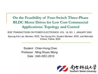
This proposed paper is to model and simulate the sensor less control of Brushless DC motor with four switch three phase inverter. Here, a new structure of three phase inverter with reduced number of switches i.e. four switch for BLDC drive is introduced to reduce the switching losses that occur in the six switch method and eliminate the mechanical commutation. Conventionally used hall sensors for position detection increase the size of the motor and are temperature sensitive since they are mounted inside. So sensor is eliminated and the back emf method is adopted for switching. The zero crossing point can be detected and it is used to commutate a motor thereby increasing the overall efficiency. Saravanakumar M | Adhithya Mannan M.B | Vinothini R | Gurusamy M "Modeling and Simulation of Cost Effective Sensor Less BLDC Motor Drive for Electric Vehicle Applications" Published in International Journal of Trend in Scientific Research and Development (ijtsrd), ISSN: 2456-6470, Volume-3 | Issue-1 , December 2018, URL: https://www.ijtsrd.com/papers/ijtsrd18952.pdf Paper URL: http://www.ijtsrd.com/engineering/electrical-engineering/18952/modeling-and-simulation-of-cost-effective-sensor-less-bldc-motor-drive-for-electric-vehicle-applications/saravanakumar-m<br>

E N D
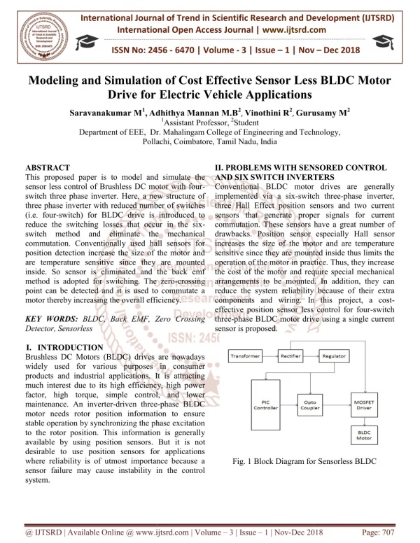
International Journal of Trend in International Open Access International Open Access Journal | www.ijtsrd.com International Journal of Trend in Scientific Research and Development (IJTSRD) Research and Development (IJTSRD) www.ijtsrd.com ISSN No: 2456 ISSN No: 2456 - 6470 | Volume - 3 | Issue – 1 | Nov 1 | Nov – Dec 2018 Modeling and Simulation of Cost Effective Sensor Less BLDC Motor Modeling and Simulation of Cost Effective Sensor Less BLDC Motor Modeling and Simulation of Cost Effective Sensor Less BLDC Motor Drive for Electric Vehicle Applications Drive for Electric Vehicle Applications Adhithya Mannan M.B2, Vinothini R2, Gurusamy M 1Assistant Professor,2Student Dr. Mahalingam College of Engineering and Technology, Pollachi, Coimbatore, Tamil Nadu, India Saravanakumar M1,Adhithya Mannan M.B Gurusamy M2 Department of EEE, Dr. Mahalingam College of Engineering and Technology, Pollachi, Coimbatore, Tamil Nadu, India Dr. Mahalingam College of Engineering and Technology, ABSTRACT This proposed paper is to model and simulate the sensor less control of Brushless DC motor with four switch three phase inverter. Here, a new structure of three phase inverter with reduced number of swi (i.e. four-switch) for BLDC drive is introduced to reduce the switching losses that occur in the six switch method and eliminate the mechanical commutation. Conventionally used hall sensors for position detection increase the size of the motor and are temperature sensitive since they are mounted inside. So sensor is eliminated and the back emf method is adopted for switching. The zero point can be detected and it is used to commutate a motor thereby increasing the overall efficiency. KEY WORDS: BLDC, Back EMF, Zero Crossing Detector, Sensorless I.INTRODUCTION Brushless DC Motors (BLDC) drives are nowadays widely used for various purposes in consumer products and industrial applications. It is attracting much interest due to its high efficiency, high power factor, high torque, simple control, and lower maintenance. An inverter-driven three motor needs rotor position information to ensure stable operation by synchronizing the phase excitation to the rotor position. This information is generally available by using position sensors. But it is not desirable to use position sensors for applications where reliability is of utmost importance because a sensor failure may cause instability in the control system. PROBLEMS WITH SENSORED CONTROL INVERTERS Conventional BLDC motor drives are generally switch three-phase inverter, three Hall Effect position sensors and two current sensors that generate proper signals for current hese sensors have a great number of sensor especially Hall sensor increases the size of the motor and are temperature sensitive since they are mounted inside thus limits the operation of the motor in practice. Thus, they increase the cost of the motor and require special mechanical ents to be mounted. In addition, they can reduce the system reliability because of their extra II. PROBLEMS WITH SENSORED AND SIX SWITCH INVERTERS Conventional BLDC motor drives are implemented via a six-switch three three Hall Effect position sensors and two current sensors that generate proper si commutation. These sensors h drawbacks. Position sensor especially Hall se increases the size of the motor and are temperature sensitive since they are mounted inside thus limits the operation of the motor in practice. the cost of the motor and require special mechanical arrangements to be mounted. In add reduce the system reliability because of their extra components and wiring. In this project, a cost effective position sensor less control for four three-phase BLDC motor drive using a single current sensor is proposed. This proposed paper is to model and simulate the sensor less control of Brushless DC motor with four- switch three phase inverter. Here, a new structure of three phase inverter with reduced number of switches switch) for BLDC drive is introduced to reduce the switching losses that occur in the six- switch method and eliminate the mechanical commutation. Conventionally used hall sensors for position detection increase the size of the motor and e temperature sensitive since they are mounted inside. So sensor is eliminated and the back emf method is adopted for switching. The zero-crossing point can be detected and it is used to commutate a motor thereby increasing the overall efficiency. In this project, a cost- effective position sensor less control for four-switch phase BLDC motor drive using a single current k EMF, Zero Crossing Brushless DC Motors (BLDC) drives are nowadays widely used for various purposes in consumer products and industrial applications. It is attracting much interest due to its high efficiency, high power factor, high torque, simple control, and lower driven three-phase BLDC motor needs rotor position information to ensure stable operation by synchronizing the phase excitation to the rotor position. This information is generally . But it is not e to use position sensors for applications where reliability is of utmost importance because a Fig. 1 Block Diagram for Sensorless BLDC Block Diagram for Sensorless BLDC in the control @ IJTSRD | Available Online @ www.ijtsrd.com www.ijtsrd.com | Volume – 3 | Issue – 1 | Nov-Dec 2018 Dec 2018 Page: 707
International Journal of Trend in Scientific Research and Development (IJTSRD) ISSN: 2456 International Journal of Trend in Scientific Research and Development (IJTSRD) ISSN: 2456 International Journal of Trend in Scientific Research and Development (IJTSRD) ISSN: 2456-6470 Table 1 Switching sequence of f Table 1 Switching sequence of four-switch three phase inverter III. PROPOSED FOUR-SWITCH THREE PHASE INVERTER BRUSHLESS DC MOTOR DRIVE Usually, Brushless DC motors are excited by Six switch three phase inverter, have lot of Commutation Problems and Switch Leg failure and large amount Switching Losses. The three-phase inverters with only four switches, is striking solution for Six Inverter to reduce mechanical Strength and Switching Losses. In additional to that with the normal three phase voltage-source inverter with Four most important descriptions of this proposed converter plays dual role, i) the first is the reduction of Switches and Freewheeling diode count; ii) the second is the reduction of conduction losses. second is the reduction of conduction losses. SWITCH THREE phase inverter Active Phases PHASE INVERTER BRUSHLESS DC MOTOR Mode Silent Phases Usually, Brushless DC motors are excited by Six- switch three phase inverter, have lot of Commutation Problems and Switch Leg failure and large amount of 1 B and C A 2 3 4 5 A and B A and C B and C A and B C B A C phase inverters with only triking solution for Six-Switch Inverter to reduce mechanical Strength and Switching Losses. In additional to that with the normal three- source inverter with Four switches, the most important descriptions of this proposed i) the first is the reduction of Switches and Freewheeling diode count; ii) the 6 A and C B IV. BACK EMF COMPENSATION As three-phase Brushless DC motor is motivated with six-step 120˚ control process. Therefore, the conduction interval of one phase is 120 EMF zero-crossing detecting performance is based on only two phases of a Brushless DC Motor. phase A and phase B are connected to the source, phase C is floating. No current is going through this phase. This conducting interval lasts 60 ele degrees, which is called commutation step. This is described by the following conditions: BACK EMF COMPENSATION phase Brushless DC motor is motivated with control process. Therefore, the conduction interval of one phase is 120˚. The Back- crossing detecting performance is based on only two phases of a Brushless DC Motor. When phase A and phase B are connected to the source, phase C is floating. No current is going through this phase. This conducting interval lasts 60 electrical ommutation step. This is conditions: Fig. 2 Four Switch three phase inverter Fig. 2 Four Switch three phase inverter In proposed method single phase to three phase converters back end consists of four switches (T1 to T6). In three phase Brushless DC motor, two phases A and B are connected to the two legs of the Four switch three phase inverter and the third phase C is connected to the centre point of the capacitor. Phase C is directly connected to the Brushless DC motor, so the phase C current is not directly controlled Sa + Sb + Sc =0 Sc=-(Sa + Sb) Therefore, phase C indirectly controlled by phase A and phase B. For Brushless DC motors with a trapezoidal back EMF, is required to produce a constant electric torque. The proposed voltage Pulse Width Modulation (PWM) scheme for Four three phase inverter requires six commutation modes which are (X, 0), (1,0), (1, X), (X, 1), (0, 1) and (0, Here “X” stands for don’t care conditions. proposed method single phase to three phase back end consists of four switches (T1 to three phase Brushless DC motor, two phases A and B are connected to the two legs of the Four- phase inverter and the third phase C is cted to the centre point of the capacitor. Phase C to the Brushless DC motor, so the phase C current is not directly controlled. Fig. 3 Simulink Model of Proposed System Fig. 3 Simulink Model of Proposed System (1) (2) If A phase High, B phase Low: which is analysed as If A phase High, B phase Low: which is analysed as general equations. Normally, £a + £b + £c = 0 Va = 3/2ew+ Vdc/2 Vb = 3/2ew+ Vdc/2 Vc = 3/2ew+ Vdc/2 In these equations, forward voltage drop of Insulated bipolar transistor and freewheeling diode is ignored. However, in the four-switch converter based on the four-switching operation, the generation of 120 conducting and a 60˚ non-conducting current profile is essentially complicated. That resource the conventional Pulse width modulation schemes conventional Pulse width modulation schemes Therefore, phase C indirectly controlled by phase A B. For Brushless DC motors with a back EMF, is required to produce a constant electric torque. The proposed voltage Pulse Width Modulation (PWM) scheme for Four-switch three phase inverter requires six commutation modes (1, X), (X, 1), (0, 1) and (0,X). care conditions. (3) (4) (5) (6) = 3/2ew+ Vdc/2 Vb = 3/2ew+ Vdc/2 Vc = 3/2ew+ Vdc/2 In these equations, forward voltage drop of Insulated bipolar transistor and freewheeling diode is ignored. tch converter based on the operation, the generation of 120˚ conducting current profile is essentially complicated. That resource the @ IJTSRD | Available Online @ www.ijtsrd.com www.ijtsrd.com | Volume – 3 | Issue – 1 | Nov-Dec 2018 Dec 2018 Page: 708
International Journal of Trend in Scientific Research and Development (IJTSRD) ISSN: 2456 International Journal of Trend in Scientific Research and Development (IJTSRD) ISSN: 2456 International Journal of Trend in Scientific Research and Development (IJTSRD) ISSN: 2456-6470 employed for four-switch induction motor drives cannot be directly applied to Brushless DC motor drives with sensor less. This lead to the improvement of a novel control scheme called Direct Current Controlled Pulse width modulation scheme V.RESULTS AND DISCUSION The simulation of proposed research four Brushless DC Motor is carried by Simulink and its Simulink model are shown in fig 3.To generate the pulse width modulation signals Subsystems proposed converter is shown in fig 4. switch induction motor drives rushless DC motor less. This lead to the improvement It is carried out by voltage and time period and the Simulink environment. The Stator Current signals generated by the switches from output of controller are shown in fig 6. It is carried out by voltage and time results are taken from Simulink Stator Current signals generated by the switches from the output of controller are shown in fig 6. of a novel control scheme called Direct Current Controlled Pulse width modulation scheme. The simulation of proposed research four-switch ed by Simulink and its To generate the Subsystems of the Fig. 6 Current Signals of phase A, B, C Fig. 6 Current Signals of phase A, B, C The Torque and Speed curves generated by the switches from the output of controller are shown in The Torque and Speed curves generated by the switches from the output of controller are shown in fig 7. Fig. 4 Subsystem of four switch inverter Fig. 4 Subsystem of four switch inverter The reference speed is set and rotor position sensor speed sensed are given to the controller. If it is it is send to the controller or error is rectified and it is given to the controller then the switches generate the Pulses. The Back e generated by the switches from the ou controller are shown in fig 5. rotor position sensor er. If it is equal oller or error is generated and is given to the controller then the The Back emf signals switches from the output of Fig. 7 Torque and Speed Characteristics Fig. 7 Torque and Speed Characteristics VI. CONCLUSION Brushless DC drives is preferable for compact, low maintenance and high reliability system reduce the mechanical strength it proposed without sensors and simulations were simulation of the brushless DC motor is done using the software MATLAB/SIMULINK phase voltage, phase current, rotor speed waveform are analysed for the speed of rotor is 800 rpm. In this proposed converter uses less number of bipolar switches which evaluate the conventional converter. The back electromotive force compensating and direct current controlling for brushless DC motor drive was leg failure was avoided. P is preferable for compact, low maintenance and high reliability systems. In order to reduce the mechanical strength it proposed that without sensors and simulations were carried out. The simulation of the brushless DC motor is done using the software MATLAB/SIMULINK. Back EMF, phase current, rotor speed waveforms the speed of rotor is 800 rpm. In this less number of insulated bipolar switches which evaluate the difference from he back electromotive force compensating and direct current controlling for was analysed and switch Pulse width modulation Fig. 5 Back Emf of phase A, B, C Fig. 5 Back Emf of phase A, B, C @ IJTSRD | Available Online @ www.ijtsrd.com www.ijtsrd.com | Volume – 3 | Issue – 1 | Nov-Dec 2018 Dec 2018 Page: 709
International Journal of Trend in Scientific Research and Development (IJTSRD) ISSN: 2456 International Journal of Trend in Scientific Research and Development (IJTSRD) ISSN: 2456 International Journal of Trend in Scientific Research and Development (IJTSRD) ISSN: 2456-6470 4)Abolfazl Halvaei Niasar, Abolfazl Vahedi, Hassan Moghbelli , “Low-cost sensor less control of four witch, Brushless DC motor drive EMF detection” Journal of Zhejiang Univers Science (ISSN 1673-565X), 565X),2009. scheme can eradicate the offset voltage in the back electromotive force signal caused by the voltage drop of the insulated bipolar transistor and also increase system efficiency by reducing the conduction loss is achieved. There are no hall sensors and system becomes robust, optimized design, efficiency and better speed. References 1)G. Paranjothi, R.Manikandan “Photovoltaic Based Brushless DC Motor Closed Loop Drive for Electric Vehicle” International Emerging Trends in Electrical and Electronics (IJETEE – ISSN: 2320-9569) Vol. 10, Issue. 1, Jan-2014. scheme can eradicate the offset voltage in the back electromotive force signal caused by the voltage drop Abolfazl Halvaei Niasar, Abolfazl Vahedi, Hassan cost sensor less control of four- Brushless DC motor drive with direct back- Journal of Zhejiang University of and also increase system efficiency by reducing the conduction loss is ved. There are no hall sensors and therefore the ecomes robust, optimized design, higher 5)Praveen Kumar C, Sobi Soman Four Quadrant Operation of Sensor less BLDC Motor” Journal of Electrical and Elec Engineering (IOSR-JEEE) JEEE), 2015. Praveen Kumar C, Sobi Soman, “Simulation of Four Quadrant Operation of Sensor less BLDC of Electrical and Electronics “Photovoltaic Based 6)Bolfazl, H.N., “A Novel Position Sensorless Control of a Four-Switch, Brushless DC Motor Drive without Phase Shifter on Power Electronics, 23, 3079 Electronics, 23, 3079-3087,2008 A Novel Position Sensorless Switch, Brushless DC Motor Shifter”, IEEE Transactions Brushless DC Motor Closed Loop Drive for International in Electrical and Electronics 9569) Vol. 10, Issue. 1, Journal Journal of of 7)Damodharan, P. and Vasudevan, K. Brushless DC Motor Drive Based on the Crossing Detection of Back Electromotive Force (EMF) from the Line Voltage Differe Transactions on Energy Conversion, 2010 Damodharan, P. and Vasudevan, K., “Sensor Less Brushless DC Motor Drive Based on the Zero- of Back Electromotive Force (EMF) from the Line Voltage Difference”, IEEE Transactions on Energy Conversion, 25, 661-668, 2)M. Ebadpour, M. B. B. Sharifian, M. R. Feyzi Cost-Effective Position Sensor Less Four-Switch Three-Phase Brushless DC Motor Drives Using Single Current Sensor” Review of Automatic Control (I.R.E.A.CO.), Vol. 4, N. 3 May 2011. M. Ebadpour, M. B. B. Sharifian, M. R. Feyzi, “A Less Control for Phase Brushless DC Motor nt Sensor” International E.A.CO.), Vol. 8)Adauria, Y., Patel, A.N., Patel, V. and Patel, J, “Simulation and Analysis of Three Phase Voltage Source Inverter Using Four Semiconductor Switches”. Nirma Conference on Engineering (NUiCONE) Engineering (NUiCONE),2012. , A.N., Patel, V. and Patel, J, Simulation and Analysis of Three Phase Voltage Using Four Semiconductor . Nirma 3)Sathish Ramachandran, Anbarasu Loganathan, “Sensor less Control of Four-SwitchInverter for Brushless DC Mot Drive and Its Simulation”, conference of Circuits and Systems , Sathish Ramachandran, Kumar Kumar Shanmugam, Krishna Krishna “Sensor less Control of Inverter for Brushless DC Motor Shanmugam, Meenakumari Kumar Kanagaraj, Kumar Kanagaraj, Meenakumari University University International International International ,May 2016. @ IJTSRD | Available Online @ www.ijtsrd.com www.ijtsrd.com | Volume – 3 | Issue – 1 | Nov-Dec 2018 Dec 2018 Page: 710