Download
1 / 69
710 likes | 964 Vues
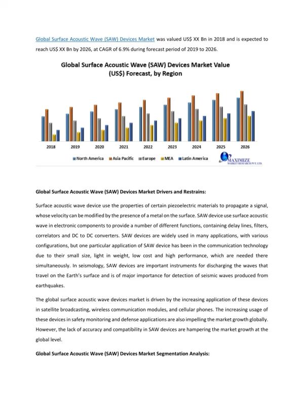
Modeling and Simulation of Surface Acoustic Wave Coupled Phase Oscillators for Sensor Applications. Shashank Shekhar Jha Sensors & Signal Processing Laboratory Department of Physics, Banaras Hindu University Varanasi – 221005, India. Supervisor : Prof. R. D. S. Yadava. Outline

E N D
Modeling and Simulation of Surface Acoustic Wave Coupled Phase Oscillators for Sensor Applications Shashank Shekhar Jha Sensors & Signal Processing Laboratory Department of Physics, Banaras Hindu University Varanasi – 221005, India Supervisor : Prof. R. D. S. Yadava
Outline • Chapter I. Introduction • −Nonlinear dynamics • −Phase oscillators • −SAW oscillators and Sensors • Chapter II. Nonlinear Dynamics of SAW Coupled Phase Oscillators • Chapter III. Phase Dynamics of Two SAW Oscillators Coupled by • Non-Dispersive SAW Delay Line • Chapter IV. Phase Dynamics of Two Non-SAW Oscillators Coupled by • Non-Dispersive SAW Delay Line • Chapter V. Synchronization Based SAW Sensors • − Sensitivity • − Noise • Chapter VI. Phase Dynamics of Two Non-SAW Oscillators Coupled by Linearly-Dispersive SAW Delay Line • Chapter VII. Phase Dynamics of Two Non-SAW Oscillators Coupled by Nonlinearly-Dispersive SAW Delay Line • Chapter VIII. Thesis Summary & Conclusion 2
Motivation • To make use of phase dynamics of delay-coupled nonlinear oscillators for sensing and chaos communication. • To investigate possibility for making high sensitivity SAW sensors by using synchronization modes in coupled phase oscillators with SAW device as coupling element.
CHAPTER - 1 Introduction
Nonlinear Dynamical System An autonomous dynamical system is described by a set ordinary differential equations of the form unknown variables analytical functions If the variables in these functions occur as first order terms only then the system is said to be linear; otherwise, if higher order terms like occur the system is said to be nonlinear. Autonomous means an isolated system that can maintain its dynamics with some internal source of energy without support from outside.
Solutions of the system define a vector space known as phase space. Fixed points are the solutions obtained by setting (condition of time-invariance) A fixed point is stable if the neighboring trajectories approach to it asymptotically as A fixed point is unstable if the neighboring trajectories move away from it as Contd… System dynamics with time is represented by the motion of phase points in phase space calledtrajectory or phase portrait.
Fixed points are classified according to the flow trajectories near a fixed point. Unstable star Contd…
Attractor Bounded region of phase space towards which nearby trajectories asymptotically approach. For examples, stable fixed points, stable limit cycle and chaotic orbits. Basin of attraction is the collection of initial conditions in phase space such that the trajectories started from them asymptotically approach the attracting orbit with time. Limit Cycle • Limit cycles are a special • type of attractors in phase • space of nonlinear system. • These are isolated closed • orbits not fixed phase points. • Limit cycles occur only in dissipative nonlinear systems. • Limit cycles are self-sustained oscillatory motion with time- • invariant amplitude.
Bifurcation The qualitative behaviour of the dynamics of a system can change with parameter variations, called bifurcation, and the parameter values for which they occur are called bifurcation points. Transcritical Bifurcationis characterised by exchange or transfer of stability of two equilibrium points at a critical value of control parameters. Pitchfork Bifurcation is characterised by the passage from one stable steady state to an unstable steady state and the simultaneous appearance of two stable steady states.
Hopf – Bifurcationis characterized by the birth of a limit cycle from an equilibrium point with the variation in control parameter. If the limit cycle is stable (unstable) then the bifurcation is supercritical (subcritical) bifurcation. Saddle – Node Bifurcation is a bifurcation of a fixed point into two equilibrium points at critical value of a control parameter with one being of saddle type and the other being stable node.
Delay Differential Equations The general form of an ordinary differential equation is: Completely determined with an initial condition A Delay Differential Equation (DDE) is a differential equation in which the derivative of the variables at some instant depends not only on the values of at that instant, but also on the values at earlier instants. That is, the system has got memory. Therefore, the solutions of DDE require knowledge of its states at previous times extending at least up to the maximum delay time involved. Discrete delay Distributed delay Time-State dependent delay “The solutions of differential equations with delay correspond to vectors in an infinite dimensional phase space because there is the need of infinitely many initial conditions.”
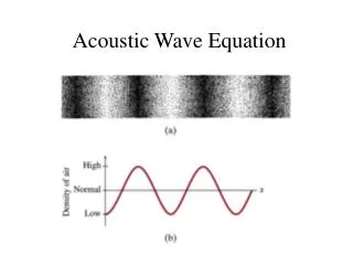
SAW Oscillator : A Phase oscillator • SAW oscillator is a delayed self-feedback nonlinear oscillator. • The equation of motion: A delay differential equation • Stable amplitude limit cycle oscillations occur if Berkhausen criteria are satisfied: and 12
SAW Delay Line Oscillator ─ a Delay Differential System In a SAW Device two interdigital transducers (IDTs) are used on piezoelectric substrates to convert electrical signal into acoustic waves (generator) and further into electrical signals (receptor). In a SAW oscillator, a SAW device is wired in the feedback path of an electronic oscillator circuit as a frequency control element. In a SAW Delay Line Sensorthe area between the generator and receptor is coated by chemically sensitive thin polymer film, the shift in oscillator frequency takes place due to molecular absorption. The shift in oscillator centre frequency is the sensor signal.
Dual SAW Delay Line Oscillator Sensor Two nearly identical SAW delay line oscillators are implemented on same substrate, one is functionalized for responding to chemicals, and the other operates as reference. The output from the two connected to a mixer circuit followed by a low-pass filter ( LPF ) generates changes in difference frequency as sensor output. The output of the mixer is the signal corresponding to vapor-polymer interaction that is sensor signal. 14
Where = A constant depending on the SAW substrate material and propagation mode, = Oscillator operating frequency h = Polymer film thickness = The polymer mass density Sensitivity The sensitivity of an oscillator chemical sensor is usually defined as the change in its fractional frequency for unit change in the stimulant quantity (chemical concentration) and is described the well known Sauerbrey`s relation: The vapor sorption in polymer produces the change in oscillator frequency via a succession of processes, the relation holds for the fractional changes in different quantities is: 15
CHAPTER - 2 Nonlinear Dynamics of SAW Coupled Phase Oscillators
& & & & The equations of motion for individual SAW delay line oscillators are: At some arbitrary instant ‘t’ after the onset of coupling interactions the signals at the input of SAW feedback devices are: The input signal at the input of two amplifiers at time ‘t’ are:
If denote the phases of two individual oscillators, the outputs of two oscillators are: Therefore the system of phase equation can be obtained as: Under weak coupling and stable amplitude assumption, the system of equations of motion for the coupled system is: SSJ and RDSY, Sens. Trans. J., 141(6), 2012
Synchronization Synchronization is an adjustment of rhythms of oscillating objects due to their weak interaction. This phenomenon is often described in terms of coincidence of frequencies as frequency entrainment or locking.. E.g. The two non-identical clocks which, if taken apart, have different oscillation periods, when coupled adjust their rhythms and start to oscillate with a common period. The phase difference between the two clocks becomes locked, called phase synchronization (In-phase synchronization) (Anti-phase synchronization)
In synchronization the phase difference between the oscillators becomes time invariant that is the rates of their phase variations become equal and both the oscillators have pulled their frequencies to a common frequency called the frequency of synchronization i. e. If denotes the phase difference of synchronized solutions then: Where the synchronization frequency is obtained by the following relationship: Contd… SSJ and RDSY, J. App. Nonl. Dyn. (Acceptd)
(A) (A) (B) (B) Chaos A phenomenon or process of occurrence of bounded non-periodic evolution in deterministic nonlinear systems with high sensitive dependence on initial conditions. Consequently nearby chaotic orbits diverge exponentially in phase space. Lyapunov Exponents Numbers providing a quantitative average measure of the divergence of nearby trajectories in phase space. All negative exponents represent regular and periodic orbits, while at least one positive exponent signals the presence of chaotic motion.
Lyapunov Stability The Lyapunov stability is defined by assuming an exponential time dependent solution of the form for linearized perturbation equations near fixed points X*. The values of all can be calculated by solving the determinant: is stable if all eigen values of have is unstable if at least one eigen value of has is a centre if all eigen values of has where denotes the diagonal elements of the Jacobian matrix of the system, calculated at fixed point 23
contd… The time-invariant solutions for the SAW coupled oscillator system, defined by , are the fixed (or equilibrium) points of the system. The stability of these synchronization points can be done by performing the usual linear stability analysis near the synchronization points by assuming small perturbations in oscillator phases of the form Where the Lyapunov exponents λ’s can be obtained by substituting Jacobian matrix in the above determinant. Jacobian is given as: On simplifying the determinant we get this transcendental characteristic equation: SSJ and RDSY, J. App. Nonl. Dyn. (Accepted)
The following four SAW coupled phase oscillators system were studied in this thesis:
Summary • Equations of motion for the SAW feedback oscillator with an amplifier having cubic nonlinearity in the voltage transfer function was derived, and the conditions for self-sustained limit cycle oscillations were established. • Equations of motion for a system of two coupled SAW limit cycle oscillators were derived where the coupling is provided by a SAW device. Assuming weak coupling the system of coupled phase equations were obtained. The system is a set of coupled delay differential equations representing autonomous coupled phase oscillators system with delayed coupling. • Assuming phase-locking or frequency synchronization the transcendental relations for the synchronization phase and frequency were obtained. • To analyze stability of the equilibrium points the equation for linear stability analysis (Lyapunov stability) was derived. • In the chapter, derivation of most basic dynamical equations of the coupled dual phase oscillators, synchronization dynamics and linear stability analysis are presented, which makes the basis for the work in the following chapters.
CHAPTER - 3 Phase Dynamics of Two SAW Oscillators Coupled by Non-Dispersive SAW Delay Line
System of phase equations: Synchronization where Stability 28
Stable Unstable MHz, MHz,
MHz, & MHz,
Conclusions • Two limit cycle SAW feedback oscillators coupled by a simple (non-dispersive) SAW delay line can be synchronized into stable limit cycle and chaotic modes of oscillation by controlling the coupling delay time, coupling strength and frequency detuning. • It has been found that: • Synchronization stability is better for smaller coupling delays. • For coupling strength lower than a threshold value there is only one • branch of synchronization exhibiting limit cycle behavior. • For self-feedback delays being much smaller than the coupling delay • there exists a window for the coupling delay for which system • remains stable for all K-values. • New synchronization branches always appear in pairs symmetrically • placed about the mean natural frequency. • By varying coupling strength the system may jump to different • chaotic attractor basins via a sequence of phase slips.
CHAPTER - 4 Phase Dynamics of Two Non-SAW Oscillators Coupled by Non-Dispersive SAW Delay Line 35
System of phase equations: Synchronization where Stability
& MHz, MHz, & MHz, MHz,
MHz, & MHz,
& MHz MHz,
Conclusions • A pair of nearly identical conventional (non-SAW) self-feedback oscillators coupled by a SAW delay line can be synchronized into several types of dynamical states: one-period to multi-period limit cycles and to chaos by controlling the coupling strength, the coupling delay and the frequency detuning. • In comparison to the SAW-coupled SAW oscillators system the SAW-coupled non-SAW (conventional) oscillators system in synchronization is less prone to fluctuations in coupling strength and frequency detuning. • At lower coupling strengths the system remains in limit cycle oscillations. • With increase in coupling strength the system makes transitions to several chaotic attractor basins via phase slips. • Regarding our main objective for synchronization mode sensing, we conclude that a pair of phase-coupled conventional non-SAW oscillators system where the coupling is provided by a SAW delay line may make a better sensing system in terms of stability and dynamic range.
CHAPTER - 5 Synchronization Based SAW Sensors 43
The sensitivity of synchronized system of SAW coupled oscillators is: The sensitivity of a conventional SAW delay line oscillator sensor is: sensitivity of synchronization mode sensor is higher when β>1, i.e. Zτc<1 Basis for Sensitivity Enhancement by “Synchronization Mode Sensing”
Noise Uncertainty in signal measurement is characterized by random frequency fluctuations called noise. The noise in a sensing oscillator defines the minimum change in sensor output (signal) that can be measured (or the minimum detection limit of the measurand). The spectral density is simply the mean square frequency fluctuation in 1-Hz bandwidth at the offset frequency. The spectral density for frequency fluctuations and phase fluctuations are related as: * It is shown theoretically and experimentally that when N identical oscillators interact on reciprocal basis the phase noise power spectral density in the synchronized state is reduced to 1/Nof a single oscillator. *A. Pikovsky et al., Synchronization: A Universal Concept in Nonlinear Sciences, Cambridge, 2003.
Contd… The phase fluctuation of a self sustained oscillator is described as a random walk or diffusion process. The noise power spectral density for a Gaussian frequency fluctuation has been found to be equal to the diffusion constant where denotes the standard deviation of frequency fluctuations. Mutual interaction of phase oscillators leading to synchronization allows randomness in their phases also to flow as easily through the coupling network and loop as their unperturbed phases. The noise for the coupled state is calculated by phase diffusion coefficients of non-interacting oscillators Diffusion coefficient:
Contd… The diffusion constant of the individual oscillators in the coupled state is If both the oscillators in their free running states have the same amount of noise power spectral density, that is In the coupled state which is ½ the noise power spectral density of the individual oscillators in free running state. * *A. Pikovsky et al., Synchronization: A Universal Concept in Nonlinear Sciences, Cambridge, 2003.
Conclusions • Higher sensitivity is obtained for small detuning and small coupling delays. • High sensitivity appears in regions beyond bifurcation point where • there are more than one nearly degenerate synchronization modes. • Noise in synchronized state is always lower than the noisiest oscillator in the natural state. • Synchronization mode sensing may provide the system shielding from parasitic influences and drifting because the presence of an internal autonomous frequency control mechanism keeps the system locked in a particular mode. • Conditions for achieving high sensitivity and low noise can be created by tuning the coupling strength and frequency detuning parameters through SAW delay device designs.