Download
1 / 6
60 likes | 78 Vues
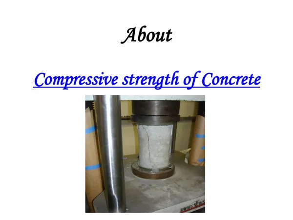
The main measure of the structural quality of concrete is its compressive strength. This property of concrete is commonly considered in structural design. Depending on the mix and time and quality of the curing, the compressive strength of concrete can be obtained up to 95 MPa or more. Commercial production of concrete with ordinarily aggregate is usually in the 20 to 80 MPa range with the most common ranges for cast in place buildings from 20 to 40 Mpa. On the other hand, precast and pre stressed applications often expect the strengths of 25 55 MPa. Although concrete is not normally designed to resist direct tension, the knowledge of tensile strength is used to estimate the load under which cracking will develop. This is imputable to its influence on the formation of cracks and its propagation to the tension side of the reinforced concrete flexural member. Shear, torsion, and other actions also produce tensile stresses to the particular section of concrete members. In most cases, member behavior changes upon cracking. So the tension strength of concrete is also considered in the proportioning concrete member. This strength is of interest in designing of highway and airfield slabs as shear strength and resistance to cracking are very important to sustain such loading. The tensile strength of concrete is relatively low, about 10 to 15 of the compressive, occasionally 20 . Priyatam Kumar | H. L. Yadav "Strength of Concrete Structure Partial Replacement of Sand by Copper Slag" Published in International Journal of Trend in Scientific Research and Development (ijtsrd), ISSN: 2456-6470, Volume-3 | Issue-5 , August 2019, URL: https://www.ijtsrd.com/papers/ijtsrd26694.pdf Paper URL: https://www.ijtsrd.com/engineering/civil-engineering/26694/strength-of-concrete-structure-partial-replacement-of-sand-by-copper-slag/priyatam-kumar<br>

E N D
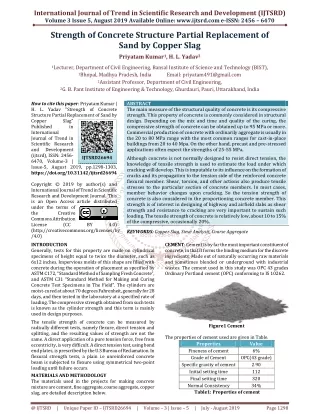
International Journal of Trend in Scientific Research and Development (IJTSRD) Volume 3 Issue 5, August 2019 Available Online: www.ijtsrd.com e-ISSN: 2456 – 6470 Strength of Concrete Structure Partial Replacement of Sand by Copper Slag Priyatam Kumar1, H. L. Yadav2 1Lecturer, Department of Civil Engineering, Bansal Institute of Science and Technology (BIST), 1Bhopal, Madhya Pradesh, India 2Assistant Professor, Department of Civil Engineering, 2G. B. Pant Institute of Engineering & Technology, Ghurdauri, Pauri, Uttarakhand, India Email: priyatam491@gmail.com How to cite this paper: Priyatam Kumar | H. L. Yadav "Strength of Concrete Structure Partial Replacement of Sand by Copper Slag" Published in International Journal of Trend in Scientific Research and Development (ijtsrd), ISSN: 2456- 6470, Volume-3 | Issue-5, August 2019, pp.1298-1303, https://doi.org/10.31142/ijtsrd26694 Copyright © 2019 by author(s) and International Journal of Trend in Scientific Research and Development Journal. This is an Open Access article distributed under the terms of the Creative Commons Attribution License (CC (http://creativecommons.org/licenses/by /4.0) INTRODUCTION Generally, tests for this property are made on cylindrical specimens of height equal to twice the diameter, such as 6x12 inches. Impervious molds of this shape are filled with concrete during the operation of placement as specified by ASTM C172, “Standard Method of Sampling Fresh Concrete”, and ASTM C31 “Standard Method for Making and Curing Concrete Test Specimens in The Field”. The cylinders are moist-cured at about 70 degrees Fahrenheit, generally for 28 days, and then tested in the laboratory at a specified rate of loading. The compressive strength obtained from such tests is known as the cylinder strength and this term is mainly used in design purposes. The tensile strength of concrete can be measured by radically different tests, namely flexure, direct tension and splitting, and the resulting values of strength are not the same. A direct application of a pure tension force, free from eccentricity, is very difficult. A direct tension test, using bond end plates, is prescribed by the U.S Bureau of Reclamation. In flexural strength tests, a plain i.e unreinforced concrete beam is subjected to flexure using symmetrical two-point loading until failure occurs. MATERIALS AND METHODOLOGY The materials used in the projects for making concrete mixture are cement, fine aggregate, coarse aggregate, copper slag, are detailed description below. ABSTRACT The main measure of the structural quality of concrete is its compressive strength. This property of concrete is commonly considered in structural design. Depending on the mix and time and quality of the curing, the compressive strength of concrete can be obtained up to 95 MPa or more. Commercial production of concrete with ordinarily aggregate is usually in the 20 to 80 MPa range with the most common ranges for cast-in-place buildings from 20 to 40 Mpa. On the other hand, precast and pre-stressed applications often expect the strengths of 25-55 MPa. Although concrete is not normally designed to resist direct tension, the knowledge of tensile strength is used to estimate the load under which cracking will develop. This is imputable to its influence on the formation of cracks and its propagation to the tension side of the reinforced concrete flexural member. Shear, torsion, and other actions also produce tensile stresses to the particular section of concrete members. In most cases, member behavior changes upon cracking. So the tension strength of concrete is also considered in the proportioning concrete member. This strength is of interest in designing of highway and airfield slabs as shear strength and resistance to cracking are very important to sustain such loading. The tensile strength of concrete is relatively low, about 10 to 15% of the compressive, occasionally 20%. KEYWORDS: Copper Slag, Sieve Analysis, Coarse Aggregate IJTSRD26694 BY 4.0) CEMENT: Cement is by far the most important constituent of concrete, in that it forms the binding medium for the discrete ingredients. Made out of naturally occurring raw materials and sometimes blended or underground with industrial wastes. The cement used in this study was OPC 43 grades Ordinary Portland cement (OPC) conforming to IS 10262. Figure1 Cement The properties of cement used are given in Table. Properties Fineness of cement Grade of Cement Specific gravity of cement Initial setting time Final setting time Normal Consistency Table1: Properties of cement Value 6% OPC(43 grade) 2.90 112 320 34% @ IJTSRD | Unique Paper ID – IJTSRD26694 | Volume – 3 | Issue – 5 | July - August 2019 Page 1298
International Journal of Trend in Scientific Research and Development (IJTSRD) @ www.ijtsrd.com eISSN: 2456-6470 FINE AGGREGATE: Aggregates which occupy nearly 70 to 75 percent volume of concrete are sometimes viewed as inert ingredients in more than one sense. However, it is now well recognized that physical, chemical and thermal properties of aggregates substantially influence the properties and performance of concrete. The fine aggregate (sand) used was clean dry sand was sieved in 4.75 mm sieve to remove all pebbles. COPPER SLAG: Copper slag is a by-product during the copper smelting and refining process. As refineries draw metal out of copper ore, they produce a large volume of non- metallic dust, soot, and rock. Copper slag which is an industrial waste obtained from smelting and refining process of copper from Sterlite Industry Ltd., Tuticorin, and Tamilnadu. Nearly 4 tons of copper is obtained as waste is disposed to lands cause’s environmental impacts. So it can be reused as concreting materials. Figure2 Fine Aggregate The Properties of fine aggregate are given in the table . Table2: Properties of fine aggregate Properties Specific Gravity Fineness Modulus Water absorption COARSE AGGREGATE: Coarse aggregate is used for making concrete. They may be in the form of irregular broken stone or naturally occurring gravel. Material which is large to be retained on 4.75mm sieve size is called coarse aggregates. Its maximum size can be up to 63mm. Figure3 Copper slag The physical properties of copper slag are shown in Table. Table4: Chemical properties of copper slag Chemical Component ical Component chemical Component ent SiO2 Fe2O3 Al2O3 CaO Na2O K2O Mn2O3 TiO2 SO3 CuO Value 2.44 2.25 1.5% % of chemical Compon% of 37.26 47.45 3.95 2.38 0.65 2.62 0.086 0.33 2.75 1.12 METHODOLOGY The aim of the experiment was to assess the properties of concrete made with Fine aggregates and copper slag to study the various important aspects such as compressive strength, flexural strength and split tensile strength of concrete Cube prepared by using Concrete materials and replacing copper slag with different percentage of replacements with cement and fine aggregate respectively. In the fresh state; the workability parameters such as slump cone test was studied. In the hardened state; the strength tests such as compressive strength, split tensile strength and flexural strength were studied. The study was carried out for mix design of Grade of concrete-M25, M30, M35 and Design- IS 10262:2009. In this study, a total of 270 numbers of concrete molds were cast. Out of which 180 cubes 150 150 150 mm, and 45 cylindrical objects casted with dimensions diameter 150mm, height-300mm and a flexural beam of 45 molds casted by dimension 150 150 700 mm. The study of this project is fully based on experimental work. In this section of the dissertation, the whole procedure or in other words we can say step by step proceedings of experimental work in an expressing way is framed. The following steps are adopted during experimental work: ?To build a structure first we need to build its base or foundations. Likewise, first of all Mix design for M25, M30, and M35 grade of concrete is prepared according to the “INDIAN STANDARDS CODE” IS 10262:2009. Figure3 Coarse aggregate Properties of Coarse aggregate are given below in table. Table3: Properties of coarse aggregate Properties Specific Gravity Size of Aggregates Fineness Modulus Water absorption Impact Test Crushing Test WATER: water plays an important role in the formation of concrete as it participates in a chemical reaction with cement. Due to the presence of water, the gel is formed which helps in increase of the strength of concrete. Almost any natural water that is drinkable and has no pronounced taste or odor can be used as mixing water. Water from lakes and streams that contain marine life are also usually suitable. Water used for mixing and curing shall be clean and free from injurious quantities of alkalies, acids, oils, salts, sugar, organic materials, vegetable growth or other substance that may be deleterious to bricks, stone, concrete or steel. Potable water is generally considered satisfactory for mixing. Values 3.125 20mm 5.96 2.0% 15.2% 22.5% @ IJTSRD | Unique Paper ID – IJTSRD26694 | Volume – 3 | Issue – 5 | July - August 2019 Page 1299
International Journal of Trend in Scientific Research and Development (IJTSRD) @ www.ijtsrd.com eISSN: 2456-6470 ?In the preparation of mix design for M25, M30, M35 grade of concrete various physical properties of the materials like specific gravity, nominal size, water absorption capacity, fineness Modulus etc. are required, also some other conditions like a type of exposure to sun and water, material mixing technique etc ?After working out the quality of different materials in an appropriate proportion, it’s time for the selection of materials. ?Keeping in mind the “INDIAN STANDARDS” materials are selected i.e., aggregates Conforming/full filling the various conditions as per IS 383:1970 and cement 53 grade OPC conforming to IS 12269:1987 are taken. ?Selected materials are mixed in a fixed proportion as per mix design to acquire the desired strength. Sampling & analysis of concrete is done according to IS 1199:1959. ?IS 2386 (Part 1): 1963 is used for the methods of tests for aggregates for concrete Specifically for the shape and size of aggregates. ?Two important tests are performed on concrete namely 1) slump cone test and 2) compaction factor test, after preparation of mix for physical properties of concrete. ?Standard moulds of size 150 mm x 150 mm x 150 mm are then cleaned and oiled Concrete is poured in the moulds and different shaped reinforcements are placed in the Moulds. ?After 24 hrs. Concrete cubes are unbolted from moulds and named with water-resistant paint and placed in the curing tank filled with normal water at 27 ± 2 0C for 28 days. ?At the end of 28 days curing it’s time for the final test which gives the actual strength of concrete i.e., compression strength test in accordance with the “INDIAN STANDARDS CODE” IS 516:1959 for the test of concrete. SIEVE ANALYSIS This test is performed to determine the percentage of different grain sizes contained within a soil. The sieve analysis is performed to determine the distribution of the coarser, larger-sized particles, and the hydrometer method is used to determine the distribution of the finer particles. Also, we can say sieve analysis used to determine the particle size distribution of sand or aggregate, which we call gradation of material. Sieve analysis of aggregates is necessary for control of the production of concrete. Sieve analysis data is useful in developing relationships concerning concrete porosity and packing. Gradation of aggregates is determined from sieve analysis, in which a representative sample of aggregate is passed through a series of sieves and the weight retained on each sieve – expressed as a percentage of the sample weight – is compared with the grading limits specified. A sieve is an apparatus – round or square in shape – with square openings, identified either by the size (clear) of the opening or by a number. The standard sieves for coarse aggregate are No.4, 3/8 in., ½ in., ¾ in., 1 in., 1 1/2 in., 2 in., and 2 1/2 in. The standard sieves for fine aggregate are nos. 100, 50, 30, 16, 8 and 4. The sizes of openings for these sieves are shown in the table. It can be seen that most of the sieves are arranged so that each has an opening size that is one-half that of the upper or twice that of the lower sieve. For example, the No. 50 sieve has an opening of 0.3-mm, which is twice the size of the opening of the No. 100 sieve (equal to 0.15-mm), and half that of the No. 30 sieve (equal to 0.6-mm). These sieves are called full sieves. Sieves that do not fall into this arrangement, such as 1 in and ½ in are called half sieves. DESIGN MIX To study the effect of copper slag substitution as a replacement for fine aggregates on the strength of cement mortars, specimens were prepared with different percentages of copper slag (by weight). Concrete mixtures with different proportions of Copper slag used as a partial or full substitute for fine aggregates were prepared in order to investigate the effect of Copper slag substitution on the strength normal concrete. Concrete mixtures were prepared with different proportions of Copper slag. The proportions (by weight) of Copper slag added to concrete mixtures were as follows: 0% (for the control mix), 5%, 10%, 15%, 20%, and 25%.The mix proportion chosen for this study is M25, M30, M35 grade with water-cement ratio of 0.42-.40. In this test total 180 Cubes of standard size 150x150x150mm and 45 Cylinders of standard diameter 150mm and height 300mm and 45 beams of size700x100x100mm were casted and cured for 7, 14, 28 and 50 days and tested as per code IS: 516-1959. The main purpose for keeping the samples for longer curing periods of 28 and 50days is to observe any detrimental effect from the use of copper slag as fine aggregate on the compressive strength and split tensile strength of concrete. TEST DETAILS In order to consider the effect of partial replacement of steel slag, the proportion of water-cement ratio, cement content, method of curing and compaction are kept constant. Cement is not replaced by Copper slag because the maximum limit of total addition of performance improver such as Copper slag, Fine aggregates, is 5 % during the manufacturing process of ordinary Portland cement as per IS 269-2013. The test samples of 1: 1.81: 3.84 concrete mix (Cement: Fine Aggregate: Coarse Aggregate) are produced with crushed granite as coarse aggregate and river sand as fine aggregate. Subsequent test samples are produced with fine and coarse aggregate, progressively replaced by Copper slag at 10% intervals, by weight, up to 50%. The water/cement ratio is kept constant at 0.55 throughout the investigation. Three number of 150 x 150 x 150 mm cubes are cast for each mix and cured in water in accordance with IS 10086- 1982. The cubes are crushed at 28 days curing age, to determine their compressive strength. The optimum percentage of replacement is found for each aggregate replacement. The further test procedure is carried out to determine the Mechanical properties such as compression, tension, flexure, deflection of RCC and the durability test such as Rapid chloride penetration test, Acid resistance using Hcl, H2SO4for that optimum percentage of replacement. To measure the workability of fresh concrete, slump test is carried out, before casting the specimens, as per IS 1199- 1959. The mold for the slump test measures bases diameter of 200 mm, while the smaller opening at the top is 100 mm and 300 mm in height. The slump cone is filled in three layers, tamping each layer 25 times with a 16 mm diameter rod to remove voids. The top surface of the concrete is leveled off. With the cone removed, the height of the slump is then measured. @ IJTSRD | Unique Paper ID – IJTSRD26694 | Volume – 3 | Issue – 5 | July - August 2019 Page 1300
International Journal of Trend in Scientific Research and Development (IJTSRD) @ www.ijtsrd.com eISSN: 2456-6470 Among various strengths of concrete, compressive strength has received a large amount of attention, because, the concrete is primarily meant to withstand compressive stress. The procedure is executed as per the IS 516- 1959, using the universal testing machine. The load is applied gradually, till the failure for the specimen. Splitting tests is well known indirect tests used for determining the tensile strength of concrete. The test consists of applying compressive line loads along with the opposite generators of a concrete cylinder placed with its axis horizontal between the patterns. Due to the applied line loading, a fairly uniform tensile stress is induced over nearly two-third of loaded diameter. Due to this tensile stress, the specimen fails finally by splitting along the loaded diameter. The determination of flexural tensile strength is essential to estimate the load at which the concrete members may crack. As it is difficult to determine the tensile strength of concrete by conducting a direct tension test, it is computed by the flexure test. The flexural tensile strength at failure or the modulus of rupture is thus determined. The computation of modulus of rupture assumes a linear behavior of the material up to failure, which is only a rough estimation. Durability tests are performed as per IS code clause 8.2.2.4 of IS 456 – 2000. Acid resistance test is done by weighing the 28 days cured specimen and the same is immersed in sulphuric acid for 90 days. The weight difference is measured after the curing period. The procedure is repeated for hydrochloric acid for different new specimens. Compressive Strength The compressive strength on each 150×150×150 Cubic specimen was determined in accordance with Compression testing machine. The two ends of each specimen were ground before testing to ensure uniform distribution of load during the test. The diameter of each specimen was taken before the compressive strength test. The testing was hydraulically controlled with a maximum capacity of 2000 KN. The load was applied to the specimen at a constant loading rate of 0.5 N until complete failure occurred. The outputs of the load cell from the testing machine were connected to a data acquisition system, which records the data during the test. The maximum load is recorded and the compressive stress computed by dividing the maximum load by the cross-sectional area of the specimen. The type of fracture was also recorded. The figure shows a cube in the testing machine before the test. ground evenly by using a grinding stone to ensure that the applied load was uniform. The flexural strength was calculated according to the type of fracture in the beam as follows: Figure6 Flexural test setup The figure shows a typical setup of the beam during testing. If the fracture initiates in the tension surface within the middle third of the span length, then modulus of rupture is calculated as follows: Where R = modulus of rupture (mm³); P = maximum applied load indicated by the testing machine (N); L = span length (mm); b = average width of the specimen (mm) at the fracture; and d = average depth of specimen (mm) at the fracture. If the fracture occurs in the tension surface outside of the middle third of the span length by not more than 5% of the span length, then modulus of rupture is calculated as follows: Where R = modulus of rupture (mm³); P = maximum applied load indicated by the testing machine (N); a = average distance between the line of fracture and the nearest support measured on the tension surface of the beam (mm); b = average width of the specimen (mm) at the fracture; and d = average depth of specimen (mm) at the fracture. If the fracture occurs in the tension surface outside of the middle third span length by more than 5% of the span length, discard the results of the test. The figure shows a typically failed beam specimen after the flexural test. Figure5 Compression test machine Flexural Strength Test The flexural strength test was run in accordance with Universal testing machine (UTN) on 150×150×700mm beam specimen at each age and the average strength was computed. Before testing, the two loading surfaces were Figure7 Beam Specimen Failure @ IJTSRD | Unique Paper ID – IJTSRD26694 | Volume – 3 | Issue – 5 | July - August 2019 Page 1301
International Journal of Trend in Scientific Research and Development (IJTSRD) @ www.ijtsrd.com eISSN: 2456-6470 Splitting Tensile Strength Test The splitting tensile strength of concrete was run in accordance with Indian Standard on cylindrical specimens (150×300mm). Four lines were drawn along the center of the cylinder to mark the edges of the loaded plane and to help align the test specimen before the application of load. The figure shows a typical setup of the cylinder during testing. A strip of wood, 3-mm thick and 25-mm wide, was inserted between the cylinder and the platens; this helped the applied force to be uniformly distributed. The load was applied and increased under a controlled rate until failure by indirect tension in the form of splitting along vertical diameter took place. Acknowledgment We would like to express our Special Thanks to Department of Civil & Environmental Engineering, National Institute of Technical Teachers Training and Research Bhopal under MHRD Government of India for offering the supports for the work. REFERENCES [1]A. O. Olanike, “A Comparative Analysis of Modulus of Rupture and Splitting Tensile Strength of Recycled Aggregate Concrete”, American Journal of Engineering Research e-ISSN: 2320-0847, Volume-03, Issue-02, pp- 141-147, 2014. [2]Anju Ramesan, Shemy S. Babu, Aswathy Lal, “Performance of lightweight concrete with plastic aggregate”, International Journal of Engineering Research and Applications, Vol. 5, Issue 8, August 2015, pp.105-110. [3]Binaya Patnaik, Seshadri Sekhar.T, Srinivasa Rao, “Strength and Durability Properties Of Copper Slag Admixed Concrete” International Journal of Research in Engineering and Technology, e-ISSN: 2319-1163, p- ISSN: 2321-7308, Volume 4, Issue 1, Feb 2015. [4]Chinmay buddhadev, Jayesh kumar pitroda, Prof. Chetna m. Vyas, “A review of innovative use of copper slag and foundry sand in design mix concrete” Journal Of International Academic Multidisciplinary, Impact Factor 1.625, ISSN: 2320- 5083, Volume 2, Issue 12, January 2015. Figure8 Splitting tensile setup Research For The figure shows a typical failed sample. The splitting tensile strength of a cylinder specimen was calculated using the following equation: [5]Jeffrey W. Bullard, Hamlin M. Jennings, Richard A. Livingston, Andre Nonat, George W. Scherer, Jeffrey S. Schweitzer, Karen L. Scrivener, Jeffrey J. Thomas, “Mechanisms of cement hydration”, Elsevier 2011. Where T = splitting tensile strength of cylinder (mm³); P = maximum applied load (N); L = average length of cylinder (mm); and D = average diameter of cylinder (mm). Conclusion: In order to consider the effect of partial replacement of steel slag, the proportion of water-cement ratio, cement content, method of curing and compaction are kept constant. Cement is not replaced by Copper slag because the maximum limit of total addition of performance improver such as Copper slag, Fine aggregates, is 5 % during the manufacturing process of ordinary Portland cement as per IS 269-2013. The test samples of 1: 1.81: 3.84 concrete mix (Cement: Fine Aggregate: Coarse Aggregate) are produced with crushed granite as coarse aggregate and river sand as fine aggregate. Subsequent test samples are produced with fine and coarse aggregate, progressively replaced by Copper slag at 10% intervals, by weight, up to 50%. The water/cement ratio is kept constant at 0.55 throughout the investigation. Three number of 150 x 150 x 150 mm cubes are cast for each mix and cured in water in accordance with IS 10086- 1982. The cubes are crushed at 28 days curing age, to determine their compressive strength. The optimum percentage of replacement is found for each aggregate replacement. The further test procedure is carried out to determine the Mechanical properties such as compression, tension, flexure, deflection of RCC and the durability test such as Rapid chloride penetration test, Acid resistance using Hcl, H2SO4for that optimum percentage of replacement. [6]K. Wille, S. El-Tawil, A.E. Naaman, “Properties of strain hardening ultra-high-performance fiber reinforced concrete (UHP-FRC) under direct tensile loading”, Elsevier, 2014. [7]Khalid Raza, Apoorv Singh, R. D. Patel, “Strength Analysis of Concrete by Using Iron Slag as A Partial Replacement of Normal Aggregate in Concrete”, International Journal of Science and Research, ISSN: 2319-7064, Volume 3 Issue 10, October 2014. [8]Kittinun Sirijaroonchai, Sherif El-Tawil, Gustavo Parra- Montesinos, “behavior of high-performance fiber- reinforced cement composites under multi-axial compressive loading”, Elsevier, 2010. [9]M. A. Rasheed, S. Suriya Prakash, “mechanical behavior of sustainable hybrid-synthetic fiber-reinforced cellular lightweight concrete for structural applications of masonry”, Elsevier, 2015. [10]M. C. G. Juenger, Rafat Siddique, “Recent advances in understanding the role of supplementary cementitious materials in concrete”, Elsevier 2015. [11]M. Etxeberria, E. Vázquez, A. Marí, M. Barra, “Influence of amount of recycled coarse aggregates and production process on properties of recycled aggregate concrete”, Elsevier 2007. [12]M. Chockalingam, D. Jayganesh, J. Vijayaraghavan, Dr. J. Jegan, “Scope for Reuse of Copper Slag in Concrete”, International Journal of Civil Engineering and @ IJTSRD | Unique Paper ID – IJTSRD26694 | Volume – 3 | Issue – 5 | July - August 2019 Page 1302
International Journal of Trend in Scientific Research and Development (IJTSRD) @ www.ijtsrd.com eISSN: 2456-6470 [17]Sukhoon Pyo, Sherif El-Tawil, Antoine E. Naaman, “Direct tensile behavior of ultra-high-performance fiber-reinforced concrete (UHP-FRC) at high strain rates”, Elsevier 2016. Technology, e-ISSN: 0976-6316, Volume 4, Issue 6, 2013. [13]P.F. Castro, A. Mendes Neto, “Assessing strength variability of concrete structural elements”, 8th International Conference of the Slovenian Society for Non-Destructive Testing, Sep. 2005. [18]Tomas U. Ganiron, “Effect of Thermoplastic as Fine Aggregate to Concrete Mixture”, International Journal of Advanced Science and Technology, Volume 62, pp.31-42, 2014. [14]Pranshu Saxena, Ashish Simalti, “Scope of Replacing Fine Aggregate with Copper Slag In Concrete” International Journal of Technical Research and Applications, e-ISSN: 2320-8163, Volume 3, Issue 4, August 2015, PP. 44-48. [19]Yi Zheng, Xuebin Jia, Kechao Zhang, Jianzhang Chend, Peng Wange, “Analysis and Experimental Study of Concrete Strength Detection”, Applied Mechanics and Materials, Volume. 351-352, 2013. [15]S. W. Tang, Y. Yao, C. Andrade, Z.J. Li, “Recent durability studies on concrete structure”, Elsevier, 2015. [20]Yuh-Shiou Tai, Sherif El-Tawil, Ta-Hsiang Chung, “Performance of deformed steel fibers embedded in ultra-high performance concrete subjected to various pullout rates”, Elsevier 2016. [16]Sahil Verma, Sahil Arora, “Replacement of Natural Sand in Concrete by Polyethylene Bottles” International Research Journal of Engineering and Technology (IRJET), Volume: 02 Issue: 01, Apr-2015. @ IJTSRD | Unique Paper ID – IJTSRD26694 | Volume – 3 | Issue – 5 | July - August 2019 Page 1303