Download
1 / 33
330 likes | 355 Vues
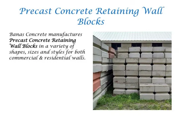
India is one of the highly populated countries of the world. It ranks the second in population next to China. Besides this, major section of the people live below poverty line. Due to over population, poverty, high land value and house deficit, major cities like Delhi and Mumbai are covered by slums. These slums not only make our country aesthetically bad but also the people living in such slums are deprived from basic facilities like proper sanitation, health care, and proper housing. The provision of affordable housing for these poor people needs to be facilitated by certain provisions. This can be possible only by introducing such technologies and materials that can be beneficial for building low cost houses. Researchers worldwide have made significant efforts to find sustainable and affordable technologies to arrest the situation. Appropriate solution for affordable housing will vary from one location to another. Some general rules, however, apply to construction methods and housing systems. This project aims for developing a technology called dry stacking or mortar less buildings made from interlocking blocks. Mortarless brick construction, usually employing interlocking bricks, is growing in popularity round the world, indicative of acceptability. Mortarless techniques demonstrate the following advantages increase of construction productivity, reduction in construction duration and labor and reduced construction cost. Because of its technological simplicity and local resource dependence, mortarless block construction is more appropriate to many local communities than conventional mortared brick techniques. Mohammad Vekas Wani | Mr. Chitranjan Kumar "Behaviour of Interlocking Hollow Concrete Blocks" Published in International Journal of Trend in Scientific Research and Development (ijtsrd), ISSN: 2456-6470, Volume-2 | Issue-4 , June 2018, URL: https://www.ijtsrd.com/papers/ijtsrd14173.pdf Paper URL: http://www.ijtsrd.com/engineering/civil-engineering/14173/behaviour-of-interlocking-hollow-concrete-blocks/mohammad-vekas-wani<br>

E N D
International Journal of Trend in Scientific Research and Development (IJTSRD) International Open Access Journal ISSN No: 2456 - 6470 | www.ijtsrd.com | Volume - 2 | Issue – 4 Behaviour of Interlocking Hollow Concrete Blocks Mohammad Vekas Wani1, Mr. Chitranjan Kumar2 1Student, 2Professor Department of Civil Engineering, Al-Falah School of Engineering and Technology Al-Falah University, Dhauj, Faridabad, Haryana, India ABSTRACT India is one of the highly populated countries of the world. It ranks the second in population next to China. Besides this, major section of the people live below poverty line. Due to over population, poverty, high land value & house deficit, major cities like Delhi & Mumbai are covered by slums. These slums not only make our country aesthetically bad but also the people living in such slums are deprived from basic facilities like proper sanitation, health care, and proper housing. The provision of affordable housing for these poor people needs to be facilitated by certain provisions. This can be possible only by introducing such technologies and materials that can be beneficial for building low-cost houses. Researchers worldwide have made significant efforts to find sustainable and affordable technologies to arrest the situation. Appropriate solution for affordable housing will vary from one location to another. Some general rules, however, apply to construction methods and housing systems. INTRODUCTION 1.1 GENRAL Masonry construction of structures offers many advantages over traditional wood framing, including increased strength, fire resistance and insulation value. Traditionally, masonry involved taking masonry manufactured cement, sand, water & aggregate, “buttering” the units with mortar, typically mixed from cement, sand water and lime, and stacking the buttered units to form a number of courses. However, this technique has a number of disadvantages. First, the weakest part of such a masonry wall is the mortar joint, as the substitution of lime for aggregate reduces the overall strength of the joint. Second, the need to butter and precisely fit each block necessitates the use of skilled, and typically highly paid, masons. Finally, the mortar used to butter the units often hardens on the inside of openings within the blocks, preventing or hindering the insertion reinforcements within the openings. One solution to the lack of strength of mortar joints has been to dry stack the masonry units. In a typical dry stacked wall, the masonry units are stacked in a staggered arrangement and are reinforced by inserting steel rebar through interlocking holes. Once reinforced, a skin made up of a fiberglass and a cementicious material may be applied to the front and back faces of the walls to provide additional reinforcement. Adding the skin to the front and back faces of the wall increases the stability of the wall by up to ten times the stability of a wall without such a skin and provides an additional barrier to prevent cold and warm air from passing through the joints between masonry units. Therefore, the use of such a skin is preferred in these types of walls. However, dry stacking of walls is not construction techniques typically units, of insulation and/or This project aims for developing a technology called dry stacking or mortar less buildings made from interlocking blocks. Mortarless brick construction, usually employing interlocking bricks, is growing in popularity round the acceptability. Mortarless techniques demonstrate the following advantages: increase of construction productivity, reduction in construction duration and labor and reduced construction cost. Because of its technological simplicity dependence, mortarless-block construction is more appropriate to many local communities than conventional mortared-brick techniques. world, indicative of and local resource @ IJTSRD | Available Online @ www.ijtsrd.com | Volume – 2 | Issue – 4 | May-Jun 2018 Page: 2850
International Journal of Trend in Scientific Research and Development (IJTSRD) ISSN: 2456-6470 without drawbacks. First, like the staking of mortar walls, care must be taken to ensure that the units are properly aligned with one another. This can be a painstaking process that greatly increases the time required to build such a wall. Second, the lack of motor in the joints between units allows air to easily pass through the joints and requires that a skin or other air barrier be used in connection with the walls. Third, the lack of mortar to hold the units in horizontal alignment make the use of many additional reinforcements, such as steel rebar, stabilizers, or the like, absolutely necessary in these types of walls. A number of masonry units for dry stacked masonry retaining walls, such as those used for landscaping, erosion prevention, or the like, have been developed. Each of these systems utilizes a tab that extends downward from each unit and engages with the back side of the unit disposed below, causing the wall to be slightly angled backward towards the earth being retained. These masonry units work well in these applications, as the force of the earth upon the blocks counterbalances the backward lean of the wall, and the backward lean provides additional stability that could not be obtained in a straight wall without the use of “dead men” or other reinforcements. However, these units are not readily adapted for use in non- retaining walls, such as those used in structures, as the backward lean produced by the stacking of the units makes these structures inherently unstable when they are not counterbalanced by the earth. Therefore, there is a need for a masonry unit and masonry system that allow structures to be dry stacked without mortar, that allows masonry units to be quickly and accurately aligned during stacking, that does not require the use of separate stabilizers or other means for preventing deflection of the structure formed thereby, that produces substantially straight and stable walls, that retards the flow of air from one face of the wall to the other, that may be manufactured of a mixture of concrete and lightweight aggregate, and that will readily accept plaster or mesh substrates upon its outside surfaces without the need for sanding or special treatment. 1.2 BACKGROUND Researchers worldwide have made significant efforts to find sustainable technologies to arrest the situation of housing solution. Appropriate solution housing will vary from one location to another. Some general rules, however, apply to construction methods and housing systems. Affordability and availability of course are the basic requirements for the low-cost housing industry cultural backgrounds and the particular needs of the communities must also be considered. With the increasing rate of unemployment in India and the natural calamities like earthquake in Gujarat,, there is still a need for labor-intensive production methods in some parts of the industry One such technology is the use of mortar less building construction. These have been in use in developing (African) countries for many years and have passed various stages of improvement in the production processes and quality of the products. 1.3 OBJECTIVES OF THE PROJECT The objectives of this project are to: ➢design a new interlocking pattern and to investigate its flexibility in terms of patterns, bonds, etc. ➢study the factors that influence the accuracy of mortar less walls. ➢Experimentally evaluate the behavior of such designed blocks in tension, compression and shear. ➢To identify experimentally best design and mix proportion of interlocking patterns that will yield optimum result. ➢Comparing the results with other interlocking designs. ➢To make it possible that the building made by these blocks should be economical and the said blocks should have good strength both in shear and compression. LITERATURE REVIEW 2.1 GENERAL A variety of interlocking type masonry building blocks are available for the construction of load bearing and non-load bearing walls. Such blocks are laid in courses without the use of mortar as done in conventional masonry. As a general rule, conventional masonry wall blocks are heavy and relatively difficult to handle. Such blocks typically include projections that mate with corresponding indentations on adjacent blocks. However, many of these projections are relatively small and thus there is an inherent weakness in the block. Also the use of small projections and small indentations means that the blocks have to be built to close tolerances which make the blocks more expensive. The typical small projections may be easily broken or chipped off prior to or during construction which means that many blocks are But, the and affordable for affordable @ IJTSRD | Available Online @ www.ijtsrd.com | Volume – 2 | Issue – 4 | May-Jun 2018 Page: 2851
International Journal of Trend in Scientific Research and Development (IJTSRD) ISSN: 2456-6470 discarded adding to the expenses. Further the available blocks do not have suitable provision for the installation of embedded utilities. Thus there is a need for masonry wall blocks that are relatively light and easier to handle, that are cost effective to manufacture and easily assembled into a more stable and dependable wall structure with provisions for embedding utilities. 2.2 POPULAR BLOCK PATTERNS 2.2.1 HAENER BLOCKS This mortar less and interlocking block has been used in thousands of structures, from simple walls to casinos and hotels. Haener offers an 8x8x16 standard size, weighing approximately 34 pounds, with an 8x8x8 half block. It also offers 6", 8" and 12" sizes. "Haener Block is a two-block building system that lays up to 10 times faster than conventional block, at a fraction of the project cost of conventional," states Larry Bouchard, Vice President of Business Development for Haener Block. "After a masonry supervisor Starts the first course level and plum, any available workers can then stack as many as 800 blocks a day each, producing perfectly self-alignment walls and corners”. and horizontal complementary surfaces when joined as components of a wall structure. Fig2. 2.Typical view of concrete hollow blocks (U. S. Pat. No. 6,105,330) 2.2.3 Verot Oaks Building Blocks, Inc. (VOBB) VOBB's dry-stacked units are based on a grid of six inches — all six inches high and six inches wide. The units are offered in 18" (22-31 pounds), 12" (15-21 pounds) and 6" lengths (7-11 pounds). "Generally, in a typical home, based on the number of doors, windows and corners, the 18" is used 85% of the time, the 12" is used 10%, and the 6" is used 5%," says John (JG) Guy, President of Verot Oaks Building Blocks. Several things distinguish the VOBB units. First, they are "rolled" while they are still green to achieve a consistent height. Also, the units use grooves and special removable clips to help keep them aligned until the grout is poured or pumped into the cavities. Fig2.1 Haener Concrete Block 2.2.2 U.S. Pat. No. 6,105,330 of Nanayakkara It discloses a construction component for use in a wall structure. The component is capable of resisting high gravity and lateral loads and is defined by a partially hollow building block having a generally solid rectangular exterior configuration in which one entire end surface of the building block exhibits a positive deep key geometry and the opposing end surface exhibits a negative deep key geometry complement to the positive geometry of the opposite end. The deep key interlocks also exhibit between opposing horizontal block surfaces as positioned between vertical cavities as the block narrows in the negative direction. In addition, there is created a substantially rugged and load resilient interlock between vertical Fig.2.3 VOBB Concrete Blocks 2.2.4 AURAM Blocks from India The technology with hollow interlocking blocks developed by the Auroville Earth Institute, which is earthquake resistant, has been approved by the Gujarat State Government. 75 presses 3000 have been supplied to Gujarat and some were operating on a @ IJTSRD | Available Online @ www.ijtsrd.com | Volume – 2 | Issue – 4 | May-Jun 2018 Page: 2852
International Journal of Trend in Scientific Research and Development (IJTSRD) ISSN: 2456-6470 continuous double-time-shift basis in the area. The average wet compressive strength achieved with the local soil stabilized with 8-9 % cement using these presses is around 50 kg/cm2 2.3.2 SIESMIC ANALYSIS OF INTERLOCKIN BLOCKS AS INFILL WALL by a journal published in IRJET: e-ISSN:2395-0056 ; p- ISSN:2395-0072, Volume 03 issue 10/oct- 2016 This research has been done to analyze the seismic behavior of interlocking blocks as infill wall. This paper compares the displacement result of frame with interlocking block wall, brick wall and a frame without any infill wall (bare wall). It has been observed that the- ➢Structure with infill wall built using interlocking block has lowest value of displacement when compared with other two models. ➢Structure with infill wall built using interlocking block has lowest value of stress when compared with other two models. 2.3.3 OVERVIEW OF WALL CONSTRUCTION MORTAR by IJIRST Volume 03/issue 10/March 2017 ISSN (online) 2349-6010 This research has been done after studying lot of research papers on interlocking blocks. This paper concludes that. If interlocking blocks are not light in weight they are difficult to place but if they are light in weight then they are easy to place. Even it has low maintenance. EPS beads and fly ash are easily available so they can be used as light weight material. Interlocking is not only effective in modern terms but in traditional way also. Use of interlocking concrete blocks the cost of labor is also negligible. With interlocking of concrete blocks we can improve the aesthetic view of building. And also the failure at joint is reduced. 2.3.4 EXPERIMENTAL INVESTIGATION ON CELLULAR LIGHTWEIGHT CONCRETE BLOCKS FOR VARYING GRADES OF DENSITY International Journal of Advanced Technology in Engineering and Science Volume 02, issue 08, aug. 2014: ISSN (online) : 2348-7550 This paper shows usage of Cellular Light-weight Concrete (CLWC) blocks gives a possible solution to building construction industry. An aim is made to study on cellular lightweight concrete blocks, and recommend as it can be used in construction industry. 2.3.5 DEVELOPMENT BUILDING BLOCKS IOSR Journal of Mechanical and Civil Engineering (IOSR- Fig 2.4Auram block 2.3 RESEARCH PAPERS 2.3.1 STRUCTURAL INTERLOCKING CONCRETE BLOCKS ISSN (e): 2250-3021, ISSN (p): 2278- 8719 IOSR JOURNAL This research paper concludes that the study was about the compressive strength analysis and cracking patterns of Interlocking pattern of concrete blocks. In this study two different types of blocks were studied. These are studied for change in compressive strength with respect to brick masonry and simple concrete masonry. It is seen that the compressive strength of this type of masonry is higher than that of both brick and concrete masonry when interlocking mortar is considered. However, it is comparable with highest grade concrete blocks of Kaushik et al in strength when the effect of the interlocking mortar is not considered. The increase in strength w.r.t. the concrete masonry hollow is by 20% and w.r.t the brick is by 40%.Besides, the increase in compressive strength is also witnessed when compared with the interlocking features. Interlocking mortar increases strength by 30% w.r.t. the prism without interlocking mortar. BEHAVIOUR OF CONCRETE BLOCK WITHOUT Fig 2.5 block patterns studied by above research OF INNOVATIVE @ IJTSRD | Available Online @ www.ijtsrd.com | Volume – 2 | Issue – 4 | May-Jun 2018 Page: 2853
International Journal of Trend in Scientific Research and Development (IJTSRD) ISSN: 2456-6470 JMCE)e-ISSN: 2278-1684, p-ISSN: 2320- 334X PP 01-07 www.iosrjournals.org The study defines that compressive and tensile strengths of lightweight concrete of density 1700 kg/m3to 1800 kg/m3 with different aluminum powder content. Based on an earlier investigation of the, cement to combined aggregate ratios of 1:6, 1:8, and 1:10 have been selected. Both sand and quarry dust have been tried as fine aggregate. Aluminum powder was added at 0.2% to 0.8% by weight of cement. For that the ultimate strength of LWC is of the range between3N/mm2–10.5N/mm2 for different aluminum powder content. Addition of more than 0.2% of aluminum powder reduces the compressive strength effectively. 2.3.6 COMPRESSION WALLS OF INTERLOCKING BRICKS MADE OF IRON ORE BY-PRODUCT AND CEMENT. International Journal of Civil & Environmental Engineering IJCEE IJENSVol: 13 No:03 This paper deals with technical assessment of the performance of walls constructed with interlocking bricks of iron ore by-products and cement under simple compressive loading. Three walls with dimensions of 150 cm width, 240 cm height and 15 cm thickness were built and tested. The first opening appear with a stress of 0.56 MPa, corresponding to only 3.8% of the rupture stress of the brick alone. Horizontal displacement was negligible in all the walls and buckling was not observed. Results showed high compressive strength of 14.57 MPa for bricks, 9.82 MPa of the prisms and 25.2 MPa of the mortar. The walls showed good mechanical strength of 2.05 MPa, which represents 14% of the brick strength. Deformations were high. And axial deformation modulus was of 420 MPa, which indicates a flexible behavior of the wall. Although the wall is flexible, the fissuration stress is relatively high .Indicating excellent performance of the wall. Another very positive aspect is that this stress is only 13.6 % of the compressive strength of the wall and 1.9% of the brick, which indicates that there is a very large strength reserve. 2.3.7 STUDY OF RED ALTERNATIVE BUILDING MATERIAL FOR INTERLOCKING BLOCKS. IJMSE International Journal of Materials Science and Engineering, Vol. 3, No. 4, pp. 295-300, December 10.17706/ijmse.2015.3.4.295-300 This study is based on behavior of interlocking blocks by using red mud for different variables. In this paper, the author is attempting to summarize the potential use of red mud in building materials of its utilization. The attention is to develop an extensive red mud form framework for building materials industry of India as it has great strength of reducing the cost of construction material & developing a low cost housing technique. 2.3.8 INTERLOCKING PARADIGM FOR CONSTRUCTION. International Journal for Research in Applied Science & Engineering Technology (IJRASET) Volume 3 Issue I, January 2015 ISSN: 2321- 9653 The study done and shown in this paper is on towards sustainability. The concept of interlocking brick and its strength parameters are checked by laboratory testing and computations method. When the comparison of interlocking brick wall with the normal brick wall, the strength and durability are more. Interlocking brick not only increases strength but also decreases the quantity of mortar required for bonding of wall units. Further the application of these type bricks used to reduce the material, reduction in environmental pollution. When the brick masonry wall is subjected to lateral forces, it fails due to shearing or overturning as the bonding is weak in horizontal directions 2.3.9 COMPARATIVE INTERLOCKING BLOCKS FOR SYSTEMS. IJRET: International Journal of Research in Engineering and Technology e ISSN: 2319-1163 | p ISSN: 2321-7308 The following specific conclusions are drawn from the statistical analysis: ➢There is significant difference between the interlocking blocks and conventional sandcrete blocks speed of construction. The interlocking blocks construction proved to be faster with better workability after laying the 1st course thereby ensuring speedy construction. ➢There is no significant difference between the interlocking blocks and conventional sandcrete blocks cost of labor. This means that in terms of 2015. doi: BRICK DESIGN- SUSTAINABLE PERFORMANCE OF www.ijraset.com STUDY AND BUILDING WALLING OF SANDCRETE MUD AS AN @ IJTSRD | Available Online @ www.ijtsrd.com | Volume – 2 | Issue – 4 | May-Jun 2018 Page: 2854
International Journal of Trend in Scientific Research and Development (IJTSRD) ISSN: 2456-6470 labor construction is within the range of the conventional sandcrete block construction. ➢There is significant difference between the costs of constructing the interlocking blocks and conventional sandcrete blocks. This suggest that interlocking blocks are affordable in favor of low cost constructions, especially in developing countries with high deposits of laetrite. ➢There is no significant difference between compressive strength of interlocking blocks and conventional sandcrete blocks. Indicating that the compressive strength of interlocking blocks is comparable to that of the conventional sandcrete blocks. 2.3.10 Journal of Civil Environmental Technology Print ISSN: 2349- 8404; Online ISSN: 2349-879X; Volume 1, Number 5; August, 2014 pp. 114–118 This research is done on a new design of interlocking pattern by the researchers of this said paper. Cement is partially replaced by fly ash to enhance certain properties. This paper concludes that this innovative interlock system is earthquake resisting .It is also faster in operation with a potential of saving over 65% of time and cost of the masonry work. It reduces wastage of materials, and gangs of labor required for operation. Interlocking blocks can be produced with the same materials as used in the production of conventional blocks. cost, the interlocking block wall entire L-wall using Engineering and Fig 2.6 pattern made by researchers of above research @ IJTSRD | Available Online @ www.ijtsrd.com | Volume – 2 | Issue – 4 | May-Jun 2018 Page: 2855
International Journal of Trend in Scientific Research and Development (IJTSRD) ISSN: 2456-6470 METHODOLOGY The methodology adopted for achieving the desired objectives is shown in the form of flow chart given below: Literature review Design of new interlocking Fabrication of moulds study of existing structures built of intrlkng Collection & testing of materials Mix design as per Is 10262:2009 Formation of interlocking blocks Physical testing of blocks Computer simulation of blocks Data collection analysis Comparison of test results Fig. 3.1 flowchart for methodology @ IJTSRD | Available Online @ www.ijtsrd.com | Volume – 2 | Issue – 4 | May-Jun 2018 Page: 2856
International Journal of Trend in Scientific Research and Development (IJTSRD) ISSN: 2456-6470 MATERIAL AND TESTING I studied different interlocking block patterns developed till now and studied their structural behavior. Furthermore I went through various research papers published in various journals. While going through various research papers I came to the conclusion that the wall straightness, stability and stiffness will be attained only if the bricks are made with good tolerance or are distorted in shape. Talking about the strength and economy, it can be enhanced by substituting cement other material like fly-ash. Keeping all the limitations of the previously designed block patterns I designed some patterns MODELS OF DIFFERENT SHAPES (DOVETAIL INTERLOCKS) Various patterns used for our project have been briefly described below a) It is a single block with a key on end and a groove on other. The outer dimensions of the block are 400mm x 200mm x 200mm. The block being hollow on inside and has a minimum thickness of 40mm from all ends. At the inner end the key has a width of 40mm, protruding out to a width of 60mm on the outer side. The key fits into the groove and this is how interlocking is achieved in the stretcher coarse. There is no top-bottom interlock, so mortar is used between coarses. Type-A Hollow block Fig. 4.1 Top view of Type-A Hollow bloc @ IJTSRD | Available Online @ www.ijtsrd.com | Volume – 2 | Issue – 4 | May-Jun 2018 Page: 2857
International Journal of Trend in Scientific Research and Development (IJTSRD) ISSN: 2456-6470 b) It is a single block with key on one end and groove on other+ key at top and grove at bottom. The block has a dimension of 400mm x 200mm x 200mm. The hollow portion is divided into two parts. The end interlocking is dovetail shaped and the top bottom interlocking is rectangular. The top-bottom interlocking is so designed to have a have overlap between coarses while constructing a wall. Again the minimum thickness of the block on each side is 40mm. The rectangular keys have a dimension of 40mm x 20mm. Distance between two inner rectangular interlocks is 20mm. Type-B Hollow block Fig. 4.3 Top view of Type-B Hollow Block Fig.4.4 3D Image of Type-B Hollow Block c) It comprises of key on one end and groove on other + two grooves on the front. The block is 400mm x 200mm x 200mm with side key and a groove as in first model. In addition to that it has two grooves on the front which makes it a female block. The front keys are also dovetail shaped as the side keys. This block has no top-bottom interlocks making it necessary to use mortar in between coarses. The block is used in the construction of a 400mm thick wall. Type-C (FEMALE) Hollow block Fig. 4.5 Top View of Type-C (FEMALE) Hollow block @ IJTSRD | Available Online @ www.ijtsrd.com | Volume – 2 | Issue – 4 | May-Jun 2018 Page: 2858
International Journal of Trend in Scientific Research and Development (IJTSRD) ISSN: 2456-6470 Fig 4.6 3D image of Type-C (FEMALE) Hollow block d)Type-C (MALE) Hollow block It consists of key on one end and groove on other + two keys on the front. The block has a dimension of 400mm x 200mm x 200mm. It is the male block for Type-C (FEMALE) block. It has a dove tail key on one end with a dovetail groove on the other end. In addition it has two dovetail keys on the front, specifying it male. The minimum thickness of the block is 40mm from all sides. It’s used with its female block for 400mm thick walls. Without top-bottom interlocks, motar is to be used between coarses. Fig. 4.7 Top View of Type-C (MALE) Hollow block Fig. 4.8 3D Image of Type-C (MALE) Hollow block e) In this type there is key and groove on sides + two grooves on front + keys on top and grooves on bottom side. The block has a dimension of 400mm x 200mm x 200mm with a groove on one side and a key on the other both being dovetail shaped. Two dovetail shaped grooves are present on the front making it of female type. It eliminates the use of motar bed completely since it is provided with rectangular keys on the top and two rectangular grooves on the bottom. The female block along with its male block is used in the construction of 400mm thick wall. Type-D (FEMALE) Hollow block @ IJTSRD | Available Online @ www.ijtsrd.com | Volume – 2 | Issue – 4 | May-Jun 2018 Page: 2859
International Journal of Trend in Scientific Research and Development (IJTSRD) ISSN: 2456-6470 Fig 4.9 (a) (b) f)Type-D (MALE) Hollow block It comprises of key on one end and groove on other + two keys on front +keys on top and grooves on bottom side. This block has dovetail shaped key on one and a groove on the other end. Two dovetail shaped keys occur on the front. Four rectangular keys are on the top and four rectangular grooves on the bottom. The size of the keys and grooves are same in all the cases and has been mentioned in the first two models. Fig. 4.10 Top View of Type-D (MALE) Hollow block Fig. 4.11 3D Images of Type-D (MALE) Hollow block @ IJTSRD | Available Online @ www.ijtsrd.com | Volume – 2 | Issue – 4 | May-Jun 2018 Page: 2860
International Journal of Trend in Scientific Research and Development (IJTSRD) ISSN: 2456-6470 MANUFACTURING FORMWORK: Formwork for desired shapes were made in steel to give the required finish and the prevent bending of formwork while casting. Six different patterns were made which are illustrated in coming section. COLLECTION OF MATERIAL: CEMENT- 43 Grade cement (AMBUJA) has been used for casting blocks. SAND – Zone 3 sand commonly available in Srinagar is used. This was determined from tests on sand done in the laboratory. AGGREGATE- Aggregates of size 6mm-10mm have been used. Aggregates of desirable size were separated by sieve analysis. MIXING IN DESIRED RATIO: The mix used is M15 (1:1.5:3). A proper mixer has been used to mix the ingredients. CASTING: The mix obtained in then filled into the moulds in three layers by 15 times tamping each layer. Vibrating table is utilized to achieve proper compaction. This prevents formation of air bubbles and a smooth surface is also obtained. Fig.4.12 Hollow blocks after casting CURING: The mould is removed after 24 hours and the block so cast is put in the curing tank. Each block is properly cured for 7 days before put to testing. TESTING: A compression test to obtain the individual compressive strength is done. To check the strength of keys, prisms were cast for each type of block and the tested in a loading frame. MATERIALS USED •Cement The cement used is ordinary Portland cement conforming to IS. Approved blended cement shall be used for internal plaster, masonry, flooring, waterproofing and plumbing works. For all RCC and PCC works, approved by fly ash shall be used. For external plaster approved fly ash as per specification of item shall be used. It shall be received in bags of 50 kg (or in bulk carriers in case of storage in silos) and each batch shall be accompanied with test certificate of the factory. Also it shall be tested before use to ascertain its strength, setting time, etc. In case cement has been stored for over 6 months from date of manufacturer or for any reasons the stored cement shows signs of deterioration or @ IJTSRD | Available Online @ www.ijtsrd.com | Volume – 2 | Issue – 4 | May-Jun 2018 Page: 2861
International Journal of Trend in Scientific Research and Development (IJTSRD) ISSN: 2456-6470 contamination, it shall be tested as per the direction of the Engineer prior to use in the works. In case blended cement is used, it shall be factory blended only (fly ash only up to 25%). •Coarse Aggregates Aggregate used is conforms to IS 383 requirements Coarse aggregate shall be obtained from natural sources such as stone, gravel etc. Crushed or uncrushed from identified and approved quarries. Aggregate shall be hard, durable, and clean and free from adherent coatings. The seasonal changes shall be well guarded. Grading shall be as indicated in IS 383. Fineness modules of the combined aggregates shall be between 3.6 and 4. The maximum size of the aggregates shall be 10mm-6mm. Coarse aggregates shall be free from harmful materials such as iron pyrites, coal, mica, shale or similar laminated material, clay, alkali, soft fragments sea shells, organic impurities etc. Impurities present within acceptable limits shall not adversely affects strength and durability. •Fine aggregate Sand used is well graded, hard, durable, clean and free from adherent coating and organic matter and shall not contain any appreciable amount clay. Sand shall not contain harmful impurities such as iron, pyrites, coal particles, lignite, mica shale or similar laminated material, alkali, and organic impurities in such form or quantities so as to affect the strength or durability of concrete or mortar. The seasonal changes shall be well guarded. Sand shall be invariably washed using screw type sand washing machine only if the silt content is not within the permissible limits. When tested as per IS 2386 part I and II, fine aggregate shall not exceed permissible quantities of deleterious materials as given. •Water Water used for mixing and curing is clean reasonably clear and free from objectionable quantities of shell, silts, alkalis, acids etc. Water tested shall be in accordance with IS 3025, Maximum permissible limits of deleterious materials in water shall be as given in IS 456. Water/cement ratio maximum used is 0.4 COMPRESSION TEST A universal testing machine (UTM), also known as a universal tester, materials testing machine or materials test frame, is used to test the tensile stress and compressive strength of materials. It is named after the fact that it can perform many standard tensile and compression tests on materials, components, and structures. The compression test was done on each individual block separately to know the behavior of each block under compressive load. The load was increased gradually and deflection at respective loads was noted down, which is given in tabulated form in next chapter. The load bearing area of each block is different so they showed different behavior to the load applied, some deformed at lower loads while some resisted to an appreciable amount of load. The compressive strength of top keys was done separately on same blocks, in which only keys were subjected to axial load & their crushing value was noted down. The following figures give a clear idea about the failure patterns on these blocks due to compression load. Fig. 4.13 Hollow block subjected to compressive load on UTM @ IJTSRD | Available Online @ www.ijtsrd.com | Volume – 2 | Issue – 4 | May-Jun 2018 Page: 2862
International Journal of Trend in Scientific Research and Development (IJTSRD) ISSN: 2456-6470 Fig. 4.14 The formation of cracks with gradual increase in axial load Fig. 4.15 The failure of key starts from bed Fig. 4.16 Vertical cracks showing critical sections of female block Fig. 4.17 Crushed Hollow Block on UTM @ IJTSRD | Available Online @ www.ijtsrd.com | Volume – 2 | Issue – 4 | May-Jun 2018 Page: 2863
International Journal of Trend in Scientific Research and Development (IJTSRD) ISSN: 2456-6470 LOADING FRAME (PRISM COMPRESSION TEST) Loading frame is an apparatus which is used to conduct flexural and compression tests on beams, columns, walls, prisms etc. it consist of I-beams which are used in making platforms for the structural members on which tests are supposed to be done. The load is given with the help of hydraulic jacks and gauges are installed on the members to be tested in order to observe the deflections in the member at respective loads. The prisms which are to be tested for compression are constructed at loading frame platform. The compressive strength is the capacity of a material or structure to withstand loads tending to reduce size. It can be measured by plotting applied force against deformation in a testing machine. Some material fracture at their compressive strength limit; others deform irreversibly, so a given amount of deformation may be considered as the limit for compressive load. Fig. 4.18 A Typical view of loading frame Fig. 4.19The prism A1 on platform of loading frame Fig.4.20 Prism installed on loading frame for compression test @ IJTSRD | Available Online @ www.ijtsrd.com | Volume – 2 | Issue – 4 | May-Jun 2018 Page: 2864
International Journal of Trend in Scientific Research and Development (IJTSRD) ISSN: 2456-6470 Concrete block compressive strength is another important characteristic which influence the concrete prism behavior that the increase in block unit strength increases the strength for both grouted and hollow prisms. For hollow prisms the increase in compressive strength is accompanied by the increase of tensile stress for block unit so as to improve the load carrying capacity for prisms. However, due to mortar confinement the lateral tensile stress develops in the blocks. Higher block strength increases the value for modulus of elasticity which induces higher lateral tensile stress. Consequently, the hollow prism strength decreases. According to this study, the increase in prism strength is not obvious when block strength reaches a certain level. For grouted prisms, the increase in prism strength with the increase of block unit strength is less than that of hollow prisms. The increase of grout strength can also increase the modulus of elasticity. It also leads to a higher vertical stress in the grout which causes higher lateral tensile stress. As a result, the increase pace of prism strength for specimen with higher grout strength is less than that of specimen with lower grout strength. COMPRESSION TEST OF PRISMS The different types of prisms which were tested on loading frame are shown in the following figures. The test was done on seven different prisms. PRISM-A1 In PRISM-A1 the two TYPE-A blocks are interlocked in a stretcher bond as shown in the figure. Then they are placed on a loading frame and uniformly distributed load is applied to the prism in the form of compression load. The load is increased gradually and deflections are noted down at respective loads. In this way stress-strain curve is plotted, which is shown in next chapter, to know the behavior of prism under compression. Loading Bearing Area = 2 x 44000 = 88000 mm2 Height of the prism = 200 mm Width of the prism = 200 mm Fig. 4.21 Typical view of PRISM-A1 PRISM-A2 In this prism the first stretcher coarse is same as PRISM-A1, but one more TYPE-A block is placed symmetrically on both blocks of first coarse on a layer of (1:4) cement-sand mortar. This block is also placed as a stretcher and this is the block which comes in contact with the load cell. When load is applied on this prism the top block tries to disperse the load on blocks @ IJTSRD | Available Online @ www.ijtsrd.com | Volume – 2 | Issue – 4 | May-Jun 2018 Page: 2865
International Journal of Trend in Scientific Research and Development (IJTSRD) ISSN: 2456-6470 underneath it, resulting in the compression failure of the prism. In this way different loads and respective deflections are noted down to determine the stress-strain curve. = 44000 mm2 Load bearing area Height of the prism = 400mm Width of the prism = 200 mm Fig. 4.22 Typical view of PRISM-A2 PRISM-B1 In this prism two TYPE-B blocks are placed on one another with keys pointing upwards interlocking in one another. The keys of top block are in direct contact with the load cell, so in order to provide uniform compressive loading on the whole block, the packing plates are used to make the top surface of prism uniform to get accurate results. The load is increased gradually and respective deflections are noted down. In this way we get stress-strain curve & stiffness of the prism. Load bearing area = 56000mm2 Height of the prism = 420 mm Width of the prism = 200 mm Fig. 4.23Typical view of PRISM-B1 PRISM-B2 In this prism the two TYPE-B blocks are placed as stretchers interlocked to one another. Then one more such block is placed on top of these two blocks such that it covers half of each block and two top keys of each block occupy the four groves of top block exactly, making it firm enough. Here also we place packing plates on top block in order to place uniform loading on the prism. The load is increased gradually and stress-Strain curves are drawn as shown in next chapter. @ IJTSRD | Available Online @ www.ijtsrd.com | Volume – 2 | Issue – 4 | May-Jun 2018 Page: 2866
International Journal of Trend in Scientific Research and Development (IJTSRD) ISSN: 2456-6470 Load bearing area = 56000mm2 Height of the prism = 420 mm Width of the prism = 200 mm Fig. 4.24 Typical view of PRISM-B2 PRISM-C1 In this prism the TYPE-C blocks (both male and female) are interlocked on front and rare side making a width of 400 mm. Since there are no top-bottom keys, so no packing plates are needed. Load is directly applied on whole prism to get stress-strain curve. = 94000 mm2 Load bearing area Height of prism = 200 mm Width of the prism = 400 mm Fig. 4.25 Typical view of PRISM-C1 PRISM-C2 In this prism in addition to PRISM-C1, one more Type-C female block is added as a header but in the same course which gets interlocked to the end keys of other two blocks. No packing plates are required as the top surface is smooth. So load is directly applied on the three block prism to determine the behaviour of various keys by stress strain curves. Load bearing area =143980 mm2 Height of the prism = 200 mm Width of prism = 400 mm @ IJTSRD | Available Online @ www.ijtsrd.com | Volume – 2 | Issue – 4 | May-Jun 2018 Page: 2867
International Journal of Trend in Scientific Research and Development (IJTSRD) ISSN: 2456-6470 Fig. 4.26 Typical view of PRISM-C2 PRISM-D In this prism the wall width is made 400 mm by interlocking male and female blocks on front and rare sides respectively. In the first course the TYPE-D (male) blocks are interlocked to one another in stretcher bond, leaving keys pointing outwards on one side of wall which are coupled with grooves of female blocks. Similarly one more coarse is laid on previous one with male block on female and female block on male. The blocks are arranged in such a way that all vertical and horizontal joints are eliminated as shown in figure. Then packing plates are used to make top surface uniform for receiving load from loading frame. In this way the behaviour of the prism to compressive loads is known. Load bearing area = 291980 mm2 Height of the prism =420 mm Width of Prism = 400 mm Fig. 4.27 Typical view of PRISM-D @ IJTSRD | Available Online @ www.ijtsrd.com | Volume – 2 | Issue – 4 | May-Jun 2018 Page: 2868
International Journal of Trend in Scientific Research and Development (IJTSRD) ISSN: 2456-6470 OBSERVATIONS & RESULTS COMPRESSIVE STRENGTH OF INDIVIDUAL BLOCKS INTERLOCKING HOLLOW CONCRETEBLOCK-TYPE-A Load Bearing Area = (400 x 200) – (300 x 120) = 44000 mm2 Peak Load (After 7 days) = 283 KN 7-day compressive strength = 283 x 103 N / 44000 mm2 = 6.43 MPa = 283 KN / 5.45 mm = 51.92 KN/mm Table 5.1Load-Deflection for Compression test of interlocking hollow block-(Type A) S.No LOAD (KN) DISPLACEMENT (mm) S.No LOAD (KN) 16 142 17 149 18 158 19 163 20 175 21 187 22 195 23 200 24 220 25 245 26 262 27 283 28 279 29 275 30 264 DISPLACEMENT (mm) 01 02 03 04 05 06 07 08 09 10 11 12 13 14 15 5 11 13 17 25 37 48 54 63 72 80 92 109 117 124 0.00 0.00 0.00 0.10 0.30 0.51 0.93 1.15 1.30 1.52 1.79 1.97 2.25 2.36 2.42 2.80 2.95 2.07 3.23 3.48 3.73 3.91 4.01 4.35 4.72 4.68 5.45 6.68 7.93 9.21 INTERLOCKING HOLLOW CONCRETE BLOCK-TYPE-B = (400 x 200) – (2 x 100 x 120) = 56000 mm2 Load Bearing Area Peak Load (After 7 days) = 454 KN = 454 x 103 N / 56000 mm2 7-day compressive strength = 8.1 MPa Stiffness (After 7 days) = Peak Load / Deflection =454 KN / 7.21 mm =62.96 KN / mm @ IJTSRD | Available Online @ www.ijtsrd.com | Volume – 2 | Issue – 4 | May-Jun 2018 Page: 2869
International Journal of Trend in Scientific Research and Development (IJTSRD) ISSN: 2456-6470 = (4 x 60 x 40) = 9600 mm2 Area of top keys Peak load taken by keys = 28 KN = 28 x 103 / 9600 mm2 7- Day Strength of keys = 2.91 MPa Table 52 Load-Deflection for Compression test of interlocking hollow block-(Type B) S.No LOAD (KN) DISPLACEMENT (mm) S.No LOAD (KN) 16 213 17 225 18 241 19 269 20 282 21 295 22 309 23 325 24 342 25 368 26 395 27 424 28 454 29 445 30 440 DISPLACEMENT (mm) 01 02 03 04 05 06 07 08 09 10 11 12 13 14 15 5 10 17 25 48 69 77 100 113 129 142 163 179 192 204 0.00 0.00 0.00 0.12 0.57 0.63 0.74 1.26 1.41 1.68 1.93 2.18 2.36 2.73 2.96 3.06 3.22 3.43 3.78 4.09 4.35 4.96 5.19 5.32 5.73 6.14 6.83 7.21 8.46 9.29 INTERLOCKING HOLLOW CONCRETE BLOCK-TYPE-C (MALE) Load Bearing Area = (400 x 200) – (300 x 120) + 20 = 44020 mm2 Peak Load (After 7 days) = 297 KN = 297 x 103 N / 44020 mm2 7-day compressive strength = 6.75 MPa Stiffness (After 7 days) = Peak Load / Deflection = 297 KN / 5.43 mm = 54.69 KN/mm @ IJTSRD | Available Online @ www.ijtsrd.com | Volume – 2 | Issue – 4 | May-Jun 2018 Page: 2870
International Journal of Trend in Scientific Research and Development (IJTSRD) ISSN: 2456-6470 Table 5.3 Load-Deflection for Compression test of interlocking hollow block-(Type C-MALE) S.No LOAD (KN) DISPLACEMENT (mm) S.No LOAD (KN) 16 152 17 165 18 178 19 192 20 202 21 222 22 238 23 255 24 270 25 282 26 297 27 280 28 275 29 268 30 250 DISPLACEMENT (mm) 01 02 03 04 05 06 07 08 09 10 11 12 13 14 15 5 12 24 33 42 50 63 75 87 93 100 105 117 130 141 0.00 0.00 0.00 0.02 0.41 0.56 0.71 0.84 0.93 1.06 1.25 1.39 1.62 1.93 2.08 2.31 2.52 2.82 3.17 3.43 3.85 4.18 4.32 4.64 4.97 5.43 6.23 7.65 9.21 11.04 INTERLOCKING HOLLOW CONCRETE BLOCK-TYPE-C (FEMALE) Load Bearing Area = (400 x 200) – (300 x 100) – 20 = 49980 mm2 Peak Load (After 7 days) = 324 KN = 324 x 103 N / 49980 mm2 7-day compressive strength = 6.48 MPa Stiffness (After 7 days) = Peak Load / Deflection = 324 KN / 5.68 mm = 57.04 KN/mm @ IJTSRD | Available Online @ www.ijtsrd.com | Volume – 2 | Issue – 4 | May-Jun 2018 Page: 2871
International Journal of Trend in Scientific Research and Development (IJTSRD) ISSN: 2456-6470 Table5.4 Load-Deflection for Compression test of interlocking hollow block-(Type-C-FEMALE) S.No LOAD (KN) DISPLACEMENT (mm) S.No LOAD (KN) 16 169 17 185 18 196 19 209 20 222 21 248 22 265 23 282 24 297 25 309 26 324 27 310 28 300 29 292 30 285 DISPLACEMENT (mm) 01 02 03 04 05 06 07 08 09 10 11 12 13 14 15 04 13 21 36 42 55 62 79 96 108 117 125 131 143 152 0.00 0.00 0.10 0.25 0.52 0.77 0.93 1.08 1.13 1.38 1.53 1.77 1.04 2.03 2.25 2.51 2.79 2.98 3.13 3.37 3.96 4.14 4.64 4.83 4.92 5.68 6.99 7.60 9.37 11.09 INTERLOCKING HOLLOW CONCRETE BLOCK-TYPE-D (MALE) = (400 x 200) – (2 x 100 x 120) +20 = 56020 mm2 Load Bearing Area Peak Load (After 7 days) = 484 KN = 484 x 103 N / 56020 mm2 7-day compressive strength = 8.64 MPa Stiffness (After 7 days) = Peak Load / Deflection =484 KN / 7.35 mm =65.85 KN/mm = (4 x 60 x 40) = 9600 mm2 Area of top keys Peak load taken by keys = 31 KN =31 x 103 / 9600 mm2 7- Day Strength of keys = 3.23 MPa @ IJTSRD | Available Online @ www.ijtsrd.com | Volume – 2 | Issue – 4 | May-Jun 2018 Page: 2872
International Journal of Trend in Scientific Research and Development (IJTSRD) ISSN: 2456-6470 Table 5.5 Load-Deflection for Compression test of interlocking hollow block-(Type D-MALE) S.No LOAD (KN) DISPLACEMENT (mm) S.No LOAD (KN) 16 256 17 275 18 291 19 309 20 331 21 352 22 377 23 395 24 412 25 430 26 456 27 484 28 470 29 463 30 450 DISPLACEMENT (mm) 01 02 03 04 05 06 07 08 09 10 11 12 13 14 15 05 17 29 45 53 75 89 100 121 139 165 184 204 221 242 0.00 0.00 0.30 0.67 1.20 1.47 1.73 2.36 2.71 3.09 3.25 3.79 4.07 4.28 4.46 4.62 4.86 5.07 5.34 5.67 5.98 6.21 6.35 6.52 6.84 7.08 7.35 8.40 9.11 11.6 INTERLOCKING HOLLOW CONCRETE BLOCK-TYPE-D (FEMALE) = (400 x 200) – (2 x 100 x 100) -20 = 59980 mm2 Load Bearing Area Peak Load (After 7 days) = 510 KN = 510 x 103 N / 59980 mm2 7-day compressive strength = 8.50 MPa Stiffness (After 7 days) = Peak Load / Deflection =510 KN / 7.27 mm =70.15 KN / mm = (4 x 60 x 40) = 9600 mm2 Area of top keys Peak load taken by keys = 29 KN =29 x 103 / 9600 mm2 7- Day Strength of keys = 3.02 MPa @ IJTSRD | Available Online @ www.ijtsrd.com | Volume – 2 | Issue – 4 | May-Jun 2018 Page: 2873
International Journal of Trend in Scientific Research and Development (IJTSRD) ISSN: 2456-6470 Table 5.6 Load-Deflection for Compression test of interlocking hollow block-Type D- (FEMALE) S.No LOAD (KN) DISPLACEMENT (mm) S.No LOAD (KN) 16 309 17 327 18 343 19 369 20 383 21 391 22 409 23 423 24 445 25 468 26 481 27 495 28 29 503 30 490 DISPLACEMENT (mm) 01 02 03 04 05 06 07 08 09 10 11 12 13 14 15 11 32 51 74 82 93 108 124 149 177 195 217 239 263 288 0.00 0.00 0.30 0.67 1.20 1.47 1.73 2.36 2.71 3.09 3.25 3.79 4.07 4.28 4.46 4.62 4.86 5.07 5.34 5.67 5.98 6.21 6.35 6.52 6.84 7.08 7.35 9.11 11.6 COMPRESSIVE STRENGTH OF PRISMS Table 5.7 Load-Deflection for Compression test for PRISM-A1 S.N O 1 2 3 4 5 6 7 8 9 10 LOAD (KN) 50 100 150 200 250 300 350 400 450 495 DISPLACEMENT (mm) 2.36 4.81 7.82 10.23 14.40 18.91 22.60 26.30 30.12 33.00 STRESS (MPa) 0.56 1.13 1.70 2.27 2.84 3.40 3.97 4.54 5.11 5.63 STRAIN 0.0118 0.0240 0.0390 0.0511 0.0720 0.0941 0.1132 0.1315 0.1506 0.1650 Fig.5.1 Stress-Strain plot of PRISM- @ IJTSRD | Available Online @ www.ijtsrd.com | Volume – 2 | Issue – 4 | May-Jun 2018 Page: 2874
International Journal of Trend in Scientific Research and Development (IJTSRD) ISSN: 2456-6470 Table 5.8 Load-Deflection for Compression test for PRISM-B1 S.NO LOAD (KN) 50 100 150 200 250 300 350 400 DISPLACEMENT (mm) 1.94 3.86 5.82 8.40 10.36 12.91 14.40 16.21 STRESS (MPa) 0.892 1.785 2.678 3.570 4.461 5.357 6.250 7.142 STRAIN 1 2 3 4 5 6 7 8 0.0046 0.0091 0.0138 0.0200 0.0246 0.0307 0.0342 0.0385 Fig.5.2 Stress-Strain plot of PRISM-B1 Table 5.9 Load-Deflection for Compression test for PRISM-B2 S.NO LOAD (KN) 50 100 150 200 250 300 350 400 DISPLACEMENT (mm) 1.34 3.86 5.82 8.20 10.33 12.90 14.40 15.91 STRESS (MPa) 0.892 1.785 2.678 3.570 4.461 5.357 6.250 7.142 STRAIN 1 2 3 4 5 6 7 8 0.0032 0.0091 0.0138 0.0195 0.0246 0.0307 0.0342 0.0385 Fig.5.3 Stress-Strain plot of PRISM-B2 @ IJTSRD | Available Online @ www.ijtsrd.com | Volume – 2 | Issue – 4 | May-Jun 2018 Page: 2875
International Journal of Trend in Scientific Research and Development (IJTSRD) ISSN: 2456-6470 Table 5.10 Load-Deflection for Compression test for PRISM-C1 LOAD (KN) 50 100 150 200 250 300 400 500 600 710 DISPLACEMENT (mm) 2.45 4.94 7.51 10.22 12.61 15.69 18.27 22.04 31.22 39.50 STRESS (MPa) 0.532 1.063 1.595 2.127 2.659 3.191 4.255 5.384 6.382 7.553 S.NO STRAIN 0.0122 0.0247 0.0376 0.0511 0.0631 0.0785 0.0914 0.1134 0.1561 0.1975 1 2 3 4 5 6 7 8 9 10 Fig 5.4 Stress-Strain plot of PRISM-C1 Table 5.11 Load-Deflection for Compression test for PRISM-C2 LOAD (KN) 100 200 300 400 500 600 700 DISPLACEMENT (mm) 2.45 4.94 7.51 10.22 12.61 15.69 18.27 STRESS (MPa) 0.532 1.063 1.595 2.127 2.659 3.191 4.255 S.NO STRAIN 0.0122 0.0247 0.0376 0.0511 0.0631 0.0785 0.0914 1 2 3 4 5 6 7 @ IJTSRD | Available Online @ www.ijtsrd.com | Volume – 2 | Issue – 4 | May-Jun 2018 Page: 2876
International Journal of Trend in Scientific Research and Development (IJTSRD) ISSN: 2456-6470 Fig.5.5 Stress-Strain plot of PRISM-C2 Table 5.12 Load-Deflection for Compression test for PRISM-D S.NO LOAD (KN) DISPLACEMENT (mm) 7.22 12.41 17.92 21.83 26.48 31.67 39.20 46.31 62.25 71.50 SRESS (MPa) STRAIN 1 2 3 4 5 6 7 8 9 10 200 400 600 800 1000 1200 1400 1600 1800 1885 0.685 1.370 2.054 2.739 3.424 4.109 4.794 5.479 6.164 6.455 0.0172 0.0295 0.0427 0.0520 0.0630 0.0754 0.0933 0.1103 0.1482 0.1702 Fig.5.6 Stress-Strain plot of PRISM-D STIFFNESS OF DIFFERENT BLOCKS & PRISMS Stiffness is the rigidity of an object — the extent to which it resists deformation in response to an applied force. The complementary concept is flexibility or pliability: the more flexible an object is, the less stiff it is. The stiffness, k, of a body is a measure of the resistance offered by an elastic body to deformation. For an elastic body with a single degree of freedom (for example, stretching or compression of a rod), the stiffness is defined as @ IJTSRD | Available Online @ www.ijtsrd.com | Volume – 2 | Issue – 4 | May-Jun 2018 Page: 2877
International Journal of Trend in Scientific Research and Development (IJTSRD) ISSN: 2456-6470 Where, F is the force applied on the body; ∂ is the displacement produced by the force along the same degree of freedom (for instance, the change in length of a stretched spring) In the International System of Units, stiffness is typically measured in Newton per meter. In Imperial units, stiffness is typically measured in pounds (lbs) per inch. Generally speaking, deflections (or motions) of an infinitesimal element (which is viewed as a point) in an elastic body can occur along multiple degrees of freedom (maximum of six DOF at a point). It is noted that for a body with multiple DOF, the equation above generally does not apply since the applied force generates not only the deflection along its own direction (or degree of freedom), but also those along other directions. For a body with multiple DOF, in order vertical displacement and a rotation relative to its unreformed axis. When there are M degrees of freedom an M x M matrix must be used to describe the stiffness at the point. The diagonal terms in the matrix are the direct-related stiffness (or simply stiffness) along the same degree of freedom and the off-diagonal terms are the coupling stiffness between two different degrees of freedom (either at the same or different points) or the same degree of freedom at two different points. In industry, the term influence coefficient is sometimes used to refer to the coupling stiffness. To calculate a particular direct-related stiffness (the diagonal terms), the corresponding DOF is left free while the remaining should be constrained. Under such a condition, the above equation can be used to obtain the direct-related stiffness for the degree of freedom which is unconstrained. The ratios between the reaction forces (or moments) and the produced deflection are the coupling stiffness. COMPARISON BETWEEN STIFFNESS OF DIFFERENT TYPES OF HOLLOW BLOCKS & THEIR PRISMS STUDIED IN THE PROJECT The final stiffness of all the blocks and their prism is plotted on following giver bar graphs, where we can compare between them and the reasons for this difference is discussed in next part of this chapter. Fig.5.7 Bar graph showing stiffness of various hollow blocks studied @ IJTSRD | Available Online @ www.ijtsrd.com | Volume – 2 | Issue – 4 | May-Jun 2018 Page: 2878
International Journal of Trend in Scientific Research and Development (IJTSRD) ISSN: 2456-6470 Fig.5.8 Bar graph showing stiffness of various hollow block prisms studied DISCUSSION 1.Stress strain graphs for different prisms have been plotted evaluating their initial stiffness and final stiffness. Initial stiffness is obtained by drawing a tangent at the lowest part on the curve. 2.Seven graphs have been plotted for different prisms constructed, from the loads and corresponding deflections. 3.These graphs give us initial and final stiffness. The initial and final stiffness for different prisms is calculated as under. Table 6.1 Initial and Final stiffness of PRISMS PRISM INITIAL STIFFNESS(KN/mm) 20.40 25.90 26.00 26.04 20.08 23.86 38.53 FINAL STIFNESS(KN/mm) PRISM A1 PRISM A2 PRISM B1 PRISM B2 PRISM C1 PRISM C2 PRISM D 15.00 17.33 22.86 24.88 17.97 20.00 26.36 As evident from the table above: 1.The initial stiffness of prism-A1 is less than prism-A2 which is because the prism-A2 is double layered increasing the stiffness of the material by 26.9%. 2.Prism- B1 has two units as in prism-A1 but due to top-bottom interlocking the mortar bed is totally eliminated hence an increase of 27.4% in initial stiffness and an increase of 52.4% in final stiffness. 3.Prism-B2 has three units no mortar is used and as such the initial stiffness has been increased by 1.5% and final by 8.88% as compared to B1. 4.Initial stiffness of C2 has increased by 18.8% as compared to C1 and final stiffness has increased by 11.2% which is due to the reason that more units have been used in C2 and also the hollow portion is less (more material) in C2. 5.Similarly the prism-D is stiffer than all other prisms both in initial and final stiffness, because there is much better interlocking between the various blocks used. In this prism all vertical and horizontal joints are avoided by interlocking. 6.The compressive strength of interlocking hollow blocks is in the range of 6-9MPa, which is @ IJTSRD | Available Online @ www.ijtsrd.com | Volume – 2 | Issue – 4 | May-Jun 2018 Page: 2879
International Journal of Trend in Scientific Research and Development (IJTSRD) ISSN: 2456-6470 better than the compressive strength of ordinary existing hollow blocks and bricks. A table to compare their strength is given below IN TABLE Table 6.2 Comparison of compressive strength of blocks DESCRIPTION COMPRESSIVE STRENGTH (7 day in MPa) 3.5 MPa 6.43 MPa 8.1 MPa 6.75 MPa 6.48 MPa 8.64 MPa 8.5MPa Hollow concrete block Interlocking block Type A Interlocking block Type B Interlocking block Type C male Interlocking block Type C female Interlocking block Type D male Interlocking block type D female The interlocking hollow block masonry have comparable strength with the ordinary hollow masonry prism which is depicted in the table below. Table 6.3 Comparison of compressive strength of prisms DESCRIPTION Ordinary hollow masonry prism Interlocking prism A1 Interlocking prism A2 Interlocking prism B1 Interlocking prism B2 Interlocking prism C1 Interlocking prism C2 Interlocking prism D PRISM STRENGTH (MPa) 7 day 5.4 – 7.54 5.62 8.86 8.70 9.46 7.55 6.45 6.44 CONCLUSION AND FUTURE SCOPE CONCLUSION Accelerated mortar-less masonry constructions have been developed or are being used in different countries with limited research studies. This project discusses first the salient features of interlocking-block masonry and then the development of simple interlocking-concrete-block masonry systems, keeping in view the requirements of shape simplicity and ease of manufacture. Testing of prisms under axial compression, loading perpendicular to bed joints were carried out on dry-stacked specimens. Interlocking-block masonry results in relatively high efficiency factors in axial compression and eccentric-to-axial capacity ratio when compared with mortar bedded masonry, thereby reducing cost, variation due to workmanship, and moisture penetration. The absence of bedding mortar also eliminates the biaxial lateral tensile stresses in masonry units which initiate early splitting at a lower stress level than its compressive strength. From the data available it is concluded that 1.The compressive strength of ordinary prisms is 5.4 – 7.54 MPa and that of interlocking blocks is 5.6 – 9.46 MPa which is much comparable in fact better the ordinary prism (39% increase). 2.The interlocking blocks results in speedier construction thereby saving money and time. 3.It eliminates mortar bed completely which otherwise proves to be the failure bed for diagonal tension. 4.It results in a labour cost reduction of up to 80%. FUTURE SCOPE The interlocking blocks that have been discussed in our project can be modified in future by: 1.The use of reinforcing bars of about 8mm diameter in the pins provided. 2.Use of steel strips or steel plates in pins. 3.Use of lateral tie rods grouted to the blocks to increase their integrity. @ IJTSRD | Available Online @ www.ijtsrd.com | Volume – 2 | Issue – 4 | May-Jun 2018 Page: 2880
International Journal of Trend in Scientific Research and Development (IJTSRD) ISSN: 2456-6470 4.Use of vertical rods in the hollow portion provided which are then held in position by grouting. This increases integrity between different coarses. 5.Use of such rods increases the tensile strength of rods thereby increasing their overall strength and hence making them useful for seismic areas as well. Fig 7.1 Placement of reinforcement in a hollow block REFERENCES 1.structural behaviour of interlocking concrete blocks issn (e): 2250-3021, issn (p): 2278- 8719 iosr journal 2.siesmic analysis of interlockin blocks as infill wall by a journal published in irjet: e- issn:2395-0056 ; p-issn:2395-0072, volume 03 issue 10/oct-2016 3.overview of concrete block wall construction without mortar by ijirst volume 03/issue 10/march 2017 issn (online) 2349-6010 4.experimental investigation on cellular lightweight concrete blocks for varying grades of density international journal of advanced technology in engineering and science volume 02, issue 08, aug 2014: issn (online) : 2348-7550 5. compression performance of walls of interlocking bricks made of iron ore by-product and cement. international journal of civil & environmental engineering ijcee ijensvol:13 no:03 6.development of innovative building blocks iosr journal of mechanical and civil engineering (iosr-jmce)e-issn: 2278-1684, p-issn: 2320-334x pp 01-07 www.iosrjournals.org 7.interlocking brick design-paradigm for sustainable construction. international journal for research in applied science & engineering technology (ijraset) www.ijraset.com volume 3 issue i, january 2015 issn: 2321-9653 8.INTERLOCKING BRICK DESIGN-PARADIGM CONSTRUCTION. International Journal for Research in Applied Science & Engineering Technology (IJRASET) www.ijraset.com Volume 3 Issue I, January 2015 ISSN: 2321- 9653 9.Journal of Civil Engineering and Environmental Technology Print ISSN: 2349-8404; Online ISSN: 2349-879X; Volume 1, Number 5; August, 2014 pp. 114–118 10.COMPARATIVE STUDY OF INTERLOCKING AND SANDCRETE BLOCKS FOR BUILDING WALLING SYSTEMS. IJRET: International Journal of Research in Engineering and Technology e ISSN: 2319-1163 | p ISSN: 2321-7308 11.US patenet no 6105330 by Nanayakkara www.uspto.gov 12.Environmental and Social Review for Fal-G bricks projects, Eco Carbon Private Limited, Jan 2006, pp.6-14. 13.M.S.Shetty, Concrete Technology, S. Chand and Company Ltd, New Delhi. 14.M.L. Gambhir, Concrete Manual, Dhanpat Rai and Sons, New Delhi. 15.Bansal Deepak, CBRI ROORKEE, India, Feb 2009. 16.Dawar Deepak, Hydraform India Pvt Ltd; www.hydraformasia.com. 17.Gujarat State Disaster Management Authority, India, Guidelines. 18.Cercorp Initiatives Inc. (2010). “FlexLock wall system {online}”. Available from http:// FOR SUSTAINABLE @ IJTSRD | Available Online @ www.ijtsrd.com | Volume – 2 | Issue – 4 | May-Jun 2018 Page: 2881
International Journal of Trend in Scientific Research and Development (IJTSRD) ISSN: 2456-6470 www.cercorp.com/ [cited 03/29 2010]. 19.“Development and Performance Evaluation of Interlocking Block-Masonry” K.B. Anand and Ramumarthy, Journal of Architectural Engineering, 2000. 20.BEHAVIOR OF CONCRETE HOLLOW-BLOCK MASONRY PRISMS UNDER AXIAL COMPRESSION By T. P. Ganesan and K. Ramamurthy 21.Behavior of Interlocking Grouted Stabilized Sand–Fly Ash Brick Masonry under Uniaxial Cyclic Compressive Loading by Maqsud E.Nazar and S. N. Sinha Design of masonry structures-Part 1-1: Common rules for reinforced and unreinforced masonry structures”, EN 1996, 131p.http://www.testmark.net/showitem-487.html. @ IJTSRD | Available Online @ www.ijtsrd.com | Volume – 2 | Issue – 4 | May-Jun 2018 Page: 2882