Download
1 / 4
40 likes | 322 Vues
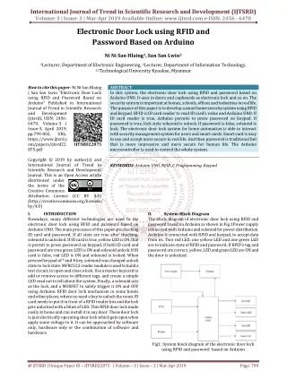
In this system, the electronic door lock using RFID and password based on Arduino UNO. It uses in doors and cupboards as electronic lock and so on. The security system is important at homes, schools, offices and industries in real life. The purpose of this paper is to develop a smart home security system using RFID and keypad. RFID is ID card reader to read ID card's value and Arduino UNO. If ID card reader is true, Arduino permits to press password on keypad. If password is true, lock style solenoid is unlock. If password is false, solenoid is lock. The electronic door lock system for home automation is able to interact with security management system for users and smart cards. Smart card is easy to use and accept more secure in real life. And then password is traditional but that is more impressive and more secure for human life. The Arduino microcontroller is used to control the whole system. Ni Ni San Hlaing | San San Lwin "Electronic Door Lock using RFID and Password Based on Arduino" Published in International Journal of Trend in Scientific Research and Development (ijtsrd), ISSN: 2456-6470, Volume-3 | Issue-3 , April 2019, URL: https://www.ijtsrd.com/papers/ijtsrd22875.pdf Paper URL: https://www.ijtsrd.com/engineering/electronics-and-communication-engineering/22875/electronic-door-lock-using-rfid-and-password-based-on-arduino/ni-ni-san-hlaing<br>

E N D
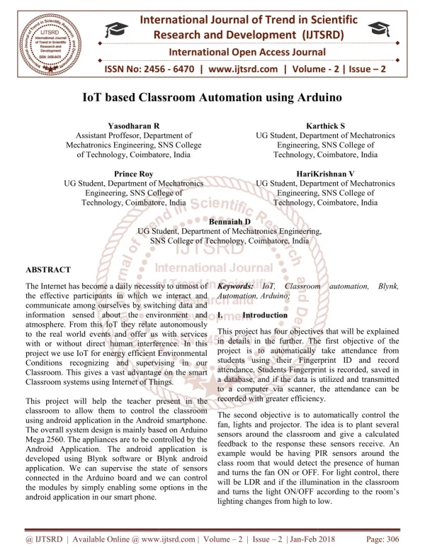
International Journal of Trend in Scientific Research and Development (IJTSRD) Volume: 3 | Issue: 3 | Mar-Apr 2019 Available Online: www.ijtsrd.com e-ISSN: 2456 - 6470 Electronic Door Lock using RFID and Password Based on Arduino Ni Ni San Hlaing1,San San Lwin2 1Lecturer, Department of Electronic Engineering, 2Lecturer, Department of Information Technology, 1,2Technological University Kyaukse, Myanmar How to cite this paper: Ni Ni San Hlaing | San San Lwin "Electronic Door Lock using RFID and Password Based on Arduino" Published in International Journal of Trend in Scientific Research and Development (ijtsrd), ISSN: 2456- 6470, Volume-3 | Issue-3, April 2019, pp.799-802, URL: https://www.ijtsrd.c om/papers/ijtsrd22 875.pdf Copyright © 2019 by author(s) and International Journal of Trend in Scientific Research and Development Journal. This is an Open Access article distributed under the terms of the Creative Commons Attribution License (CC BY 4.0) (http://creativecommons.org/licenses/ by/4.0) I. INTRODUCTION Nowadays, many different technologies are used to the electronic door lock using RFID and password based on Arduino UNO. The main processes of this paper are checking ID card and password. If all state are true after checking, solenoid is unlocked. If ID card is true, yellow LED is ON, that is permit to press password on keypad, if both ID card and password are true green LED is ON and solenoid unlock. If ID card is false, red LED is ON and solenoid is locked. When pressed keypad of * and # key, solenoid was changed unlock state to lock state. MFRC522 reader module is used to build a test circuit, to open and close a lock. Use a master keycard to add or remove access to different tags, and create a simple LED read out to tell about the system. Finally, a solenoid acts as the lock, and a MOSFET to safely trigger it ON and OFF using Arduino. RFID door lock mechanism in some hotels and other places, where no need a key to unlock the room. ID card needs to put it in front of a RFID reader box and the lock gets unlocked with a blink of LED. This RFID door lock made easily at home and can install it in any door. These door lock is just electrically operating door lock which gets open when apply some voltage to it. It can be approached by software only, hardware only or the combination of software and hardware. ABSTRACT In this system, the electronic door lock using RFID and password based on Arduino UNO. It uses in doors and cupboards as electronic lock and so on. The security system is important at homes, schools, offices and industries in real life. The purpose of this paper is to develop a smart home security system using RFID and keypad. RFID is ID card reader to read ID card’s value and Arduino UNO. If ID card reader is true, Arduino permits to press password on keypad. If password is true, lock style solenoid is unlock. If password is false, solenoid is lock. The electronic door lock system for home automation is able to interact with security management system for users and smart cards. Smart card is easy to use and accept more secure in real life. And then password is traditional but that is more impressive and more secure for human life. The Arduino microcontroller is used to control the whole system. KEYWORDS: Arduino UNO, RFID, C Programming, Keypad IJTSRD22875 II. The block diagram of electronic door lock using RFID and password based on Arduion as shown in Fig.1Power supply connected with Arduino and solenoid for power distribution. Arduino is connected with RFID and keypad, to accept data from its. Two red LED, one yellow LED and one green LED are to indicate state of RFID and password. If RFID’s tag and password are correct, yellow, LED and green LED are ON and the door is unlocked. System Block Diagram Fig1: System block diagram of the electronic door lock using RFID and password based on Arduion @ IJTSRD | Unique Paper ID – IJTSRD22875 | Volume – 3 | Issue – 3 | Mar-Apr 2019 Page: 799
International Journal of Trend in Scientific Research and Development (IJTSRD) @ www.ijtsrd.com eISSN: 2456-6470 The flowchart shown in Fig.2 is for the operation of the system. In this system, Arduino UNO is used as the main of control system. The microcontroller is used as the function of condition checking and then used as the solenoid door lock hardware controller. Six pins of analog pin and two pins of digital input/output pin are connected with keypad and five input/output pins for RFID receiver. Digital input/output pin number 6 is connected with TIP 122 transistor for driving solenoid lock hardware. And then four LEDs is use for indicate condition state, Arduino digital I/O pin number 4 is yellow LED, pin number 5 is red LED, pin 6 is green LED and pin 7 is red LED. The decision making of the microcontroller is depended on the condition of the RFID and user input password correction state. In this system, the motion of the solenoid door lock is always dependent on the decision making according to the RFID and keypad password of the controller. If the user input RFID tag is correct, the controller permit to press keypad password for user and both RFID tag and user input password are correct, controller drive solenoid door lock III. A.Implementation using Arduino UNO In this paper, the programming software is proposed for control functions in the system. The control system has the ability to perform the full responsibilities. The programming software of the system is Arduino C programming software. A program is text that user write using a programming language that contains behaviours that need a processor to acquire. It basically creates a way of handling inputs and producing outputs according to these behaviours. It is often defined as a general purpose programming language and is indeed one of the most used languages of all times. It had been used initially to design the UNIX operating system that had numerous requirements, especially high performance. This is decision making with if statement for RFID tag’s internal serial ID. If user’s RFID tag number is same with system’ statement RFIDC will true and pin number 4’s yellow LED is ON and red is OFF, controller will permit to press keypad for user. Implementation Fig 3: Decision Making for Correct RFID Tags Fig 4: Decision Making for Wrong RFID Tags And then, other condition are checked with else if again and again. If these of following conditions are true statement of each condition will be working. The else statement is for incorrect tags state. The works of else are variable RFIDC to false and Arduino pin 4 is LOW and pin 5 is HIGH. If RFID tags are correct the boolean variable RFIDC is true and read Keypad ( ) method is work. Fig 2: Flowchart of the system. @ IJTSRD | Unique Paper ID - IJTSRD22875 | Volume – 3 | Issue – 3 | Mar-Apr 2019 Page: 800
International Journal of Trend in Scientific Research and Development (IJTSRD) @ www.ijtsrd.com eISSN: 2456-6470 B.Implementation by Hardware Fig 5: Reading User of Input on Keypad Fig 8: Overall Circuit Diagram of the system 1.Electronic door lock using RFID and password based on Arduino system: RFID receiver has eight connector pins that are SDA, SCK, MOSI, MISO, RQ, GND, RST and VCC. SDA to Arduino pin 10, SCK to Arduino pin 13, MOSI to Arduino pin 11, MISO to Arduino pin 12, RQ is not used, GND is Arduino GND, RST is Arduino pin 9 and VCC is Arduino 3.3V pin. RFID receiver work to receive data from RFID tags. And then, Arduino will check that tag data. If these tags are correct, Arduino accept to press keypad and yellow LED is ON and tags are not correct red LED is ON and Arduino is not accepted to press keypad. The keypad has eight I/O pins and that are R1, R2, R3, R4, C1, C2, C3 and C4. R1 is Arduino A0, R2 is Arduino A1, R3 is Arduino A2, R4 is Arduino A3, C1 is Arduino A4, C2 is Arduino A5, C3 is Arduino pin 3 and C4 is Arduino pin 2. If RFID tags are correct and Arduino is allowed to press keypad. This paper is door password and activate key is # and clear password key is *. When user wants to close the door, presses * and #. If keypad password is correct, green LED is ON and Arduino pin 8 is HIGH, so electric current pass from Arduino pin to resistor 10kΩ and transistor’s Tip 122 base pin. And then, the transistor permitted current from collector to emitter so the solenoid lock hardware is drive. 2.Circuit Operation of Power Supply In read Keypad ( ) method, the char type variable key is to get from keypad press values. And, these are check with keypad press or no press if keypad is press user’s input key is checked by switch statement.* for all password clear,# for calling check Key method and checking password true or false. And default is sent in user’s keypad pressing number into attempt [ ] array. If user pressed # key, program will called check Key ( ); method. Fig 6: Decision Making for User Input Password In the checKey( ) method, integer variable correct is 0 to store correct password. The for loop is to match user input password and system correct password, if the four password are correct the integer variable correct is 4 and correct Key ( ) method is work. It is not true incorrect Key ( ) method is work. And then other for loop is clear all password like a zero. Fig 9: Power Supply First, power supply is one of the main parts of this paper because it distributes power for that paper. On this power supply has nine components. These are 220V to 15V step down transformer, rectifier diode (1N4007), 1000µF capacitor, 1kΩ resistor, red LED and 7805 voltage regulator IC.220V to 15V step down transformer make for reducing voltage. Transformer’s secondary is 15V AC but this thesis’s electric circuit can only work with DC (Direct Current) so use to four rectifier diode for converting to DC like a full wave design. Now, this circuit gets DC from a full wave rectifier diode but it isn’t smooth to use. So, 1000µF capacitor uses to current smother like a wave filter. 1000µF capacitor is recommended. Red LED indicates the power state of this power supply that generated over 15V or under 15V. LED can’t accept this current because LED can only work with under 3V and 20mA. Now, this power supply voltage is under 15V or over 15V, this can damage for LED. So, this Fig 7: Checking for User Password Correct and Incorrect State When the user’s password is correct with system correct password the correct Key ( ) method is work. In this method, Arduino pin 8 is HIGH and 7 is LOW. Arduino pin 8 connected both green LED and solenoid door lock hardware driver transistor. If the user’s password and system correct password are not match. Process is not true, so RFIDC variable is false and Arduino pin number 4 is LOW (yellow LED), pin 5 is HIGH (red LED), pin 8 is LOW (green LED) and pin 7 is HIGH (red LED) @ IJTSRD | Unique Paper ID - IJTSRD22875 | Volume – 3 | Issue – 3 | Mar-Apr 2019 Page: 801
International Journal of Trend in Scientific Research and Development (IJTSRD) @ www.ijtsrd.com eISSN: 2456-6470 paper used 1kΩ resistor to reduce voltage and current of power supply for LED. And then to produce 12V stable voltage that used 7812 (12V regulator IC). It gives stable 12V and 7805 to use for getting stable 5V. 7805 IC is produced stable 5V for Arduino input power. 7085 pin out for Arduino VIN and GND pin for Arduino GND. 7812 voltage regulator produce stable 12V to drive solenoid door lock. IV. Results Arduino based electronic door lock system is very smart and secure device in real world. RFID receiver is receiving data from RFID tags and Arduino determined that data true or false. And then password is protected in this system for more secure. For power distribute for this system 220V to 15V power supply and 12V to solenoid and 5V for Arduino. User need more power ampere because in this system’s solenoid and 5V for Arduino. V. This paper is discussed about the development of RFID checking and password control system by Arduino. An electronic door lock system for home automation is designed for using passwords and RFID control door lock. This is introduced using RFID and keypad for controlling door lock system. An electronic door lock system for home automation is successfully constructed for this paper. This paper is described RFID and password using with Arduino along the path. This is contained DC solenoid door lock driver circuit, DC solenoid door lock, keypad and RFID. C programming language is used to control DC solenoid door lock driver. This paper is emphasized theoretical aspects of design and construction control system. VI. Conclusion In this system is designed with the electronic door lock using RFID and password based on Arduino UNO. Electronic lock systems are preferable over mechanical locks, to resolve the security problems that are associated with the mechanical locks. An electronic door lock system for home automation was developed in this paper. Arduino microcontroller is used as a main controller. Arduino is amazingly useful device. They are used for a wide range of application. Arduino needs other components for receiving and sending data must be added to it. Arduino is designed to be all of that on it and it is used for the more cost effective in education and industrial applications. VII. REFERENCES [1]Aidan, Controlling a solenoid with an Arduino, 08 June (2016). https://core-electronics.com.au/turo- rials/solenoid-control-with arduino.htm/ Discussion Fig 10: Correct RFID Tag State [2]Krishna, P.: How to set up a keypad on Arduino, Circuit Basics (2013). Fig 11: Correct Password State [3]http://www.circuitbasics.com/how-to-set-up-a- keypad-on-an-arduino/ [4]http://www.rfidjournal.com/article/articleview/1741 /1/1/ [5]Rui, S.: Security Access using MFRC522 RFID Reader with Arduino, RANDOM NERD (2012). [6]https://randomnerdtutorials.com/security-access- using-mfrc522-rfid-reader-with-arduino/ Fig 12: No Power State [7]Alan, G.: Margolis, Introduction to Arduino, a piece of cake, Arduino Cookbook, O'reilly, CA, USA, (2011). [8]Paul, S.: and Simon, M.: PRACTICAL ELECTRONICS FOR INVERTORS, (2008). [9]Brian, W.: Arduino Programming Notebook, First edition (2007). [10]http://arduino.cc/tutorial Fig 13: Configuration of the Power ON State [11]Finkenzeller, K.: RFID Handbook “Fundemantals and applications in Contactless Smart Cards and Identification”, Wiley & Sons LTD ISBN 0-470-84402-7 (2003). Fig 14: Configuration of Finish and Installation @ IJTSRD | Unique Paper ID - IJTSRD22875 | Volume – 3 | Issue – 3 | Mar-Apr 2019 Page: 802