Fire Fighting Robot System
80 likes | 230 Vues
Increasing human population and technological development has led to increase in fire accidents and hazards. Adverse conditions and physical limitations of human being make fire extinguishing challenging and demanding task. Fire extinguishing is very risky task and it involves loss of life. Robotics is the emerging solution to protect the surrounding and human lives. Fire extinguishing robot is a hardware model which is used for extinguishing the fire during fire accidents. It reduces the errors and limitations faced by the humans during fire extinguishing task. In this paper includes Arduino UNO, fire sensor, servo motor, motor driver, water level sensor and water pump. The vehicle consists of a water tank along with a pump which throws water when needed. The system uses an Arduino UNO microcontroller board for this purpose. The fire sensor on the vehicle is used to receive the amount of fire. These values are used to find the location of the fire. These are then fed to the motors responsible for controlling the vehicle movements in front, back, left and right directions. The fire sensor is interfaced with an Arduino UNO microcontroller for this purpose. The microcontroller after receiving input commands operates the motors through a motor driver for vehicle movements. It also uses a water pump which is used to spray water with a desired pressure. Khin Thandar Tun | Hay Man Oo | Su Mon Aung "Fire Fighting Robot System" Published in International Journal of Trend in Scientific Research and Development (ijtsrd), ISSN: 2456-6470, Volume-3 | Issue-5 , August 2019, URL: https://www.ijtsrd.com/papers/ijtsrd27854.pdf Paper URL: https://www.ijtsrd.com/engineering/electronics-and-communication-engineering/27854/fire-fighting-robot-system/khin-thandar-tun<br>

Fire Fighting Robot System
E N D
Presentation Transcript
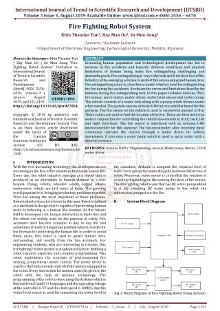
International Journal of Trend in Scientific Research and Development (IJTSRD) Volume 3 Issue 5, August 2019 Available Online: www.ijtsrd.com e-ISSN: 2456 – 6470 Fire Fighting Robot System Khin Thandar Tun1, Hay Man Oo1, Su Mon Aung2 1Lecturer, 2Assistant Lecturer 1,2Department of Electronic Engineering, Technological University, Meiktila, Myanmar How to cite this paper: Khin Thandar Tun | Hay Man Oo | Su Mon Aung "Fire Fighting Robot System" Published in International Journal of Trend in Scientific Research and Development (ijtsrd), ISSN: 2456- 6470, Volume-3 | Issue-5, August 2019, pp.2101-2105, https://doi.org/10.31142/ijtsrd27854 Copyright © 2019 by author(s) and International Journal of Trend in Scientific Research and Development Journal. This is an Open Access article distributed under the terms of the Creative Commons Attribution License (CC (http://creativecommons.org/licenses/by /4.0) I. INTRODUCTION With the ever increasing technology, the developments are increasing in the face of the situations that cause human life. Every day, the robot industry emerges as a model that is produced as an alternative to human element in a new branch. Flying, robots, wheeled robots, legged robots; underwater robots are just some of them. The growing world population is bringing involuntary problems together. Fires are among the most important of these problems. Robot industry has a lot of work in this area. Robot is defined as a mechanical design that is capable of performing human tasks or behaving in a human like manner. As the robotic field is developed a lot, human interaction is made less and the robots are widely used for the purpose of safely. Fire accidents have become common in day to day life and sometimes it leads to dangerous problem which is harder for the fireman for protecting the human life. In order to avoid these cases, this robot is used to guard human lives, surrounding, and wealth from the fire accidents. For engineering students, who are interesting in robotics, this fire fighting? Robot system is an advanced system. Building a robot requires expertise and complex programming. This robot implements the concepts of environmental fire sensing, proportional motor control. The motor driver is used for the bidirectional control of the motors equipped in the robot. Every instruction for motion control is given to the robot with the help of Arduino technology. The programming of the robot is done using the Arduino which is derived from C and C++ languages and the operating voltage of the controller is 5V and the clock speed is 16MHz. And the water level sensor is used for measuring the water level in ABSTRACT Increasing human population and technological development has led to increase in fire accidents and hazards. Adverse conditions and physical limitations of human being make fire extinguishing challenging and demanding task. Fire extinguishing is very risky task and it involves loss of life. Robotics is the emerging solution to protect the surrounding and human lives. Fire extinguishing robot is a hardware model which is used for extinguishing the fire during fire accidents. It reduces the errors and limitations faced by the humans during fire extinguishing task. In this paper includes Arduino UNO, fire sensor, servo motor, motor driver, water level sensor and water pump. The vehicle consists of a water tank along with a pump which throws water when needed. The system uses an Arduino UNO microcontroller board for this purpose. The fire sensor on the vehicle is used to receive the amount of fire. These values are used to find the location of the fire. These are then fed to the motors responsible for controlling the vehicle movements in front, back, left and right directions. The fire sensor is interfaced with an Arduino UNO microcontroller for this purpose. The microcontroller after receiving input commands operates the motors through a motor driver for vehicle movements. It also uses a water pump which is used to spray water with a desired pressure. KEYWORDS: Arduino UNO, C Programming, Sensors, Water pump, Motors, L293D motor driver IJTSRD27854 BY 4.0) the container. Arduino is assigned the required level of water level sensor for controlling the backward direction of robot. Moreover, servo motor is controlled the rotation of container depending on the sensing direction of fire sensor. The fire fighting robot is one that has DC water pump added to it. By attaching DC water pump to the robot, the automation pumped out the fire. II. System Block Diagram Water Pump Power supply Arduino UNO Water level sensor Fire sensor Servo motor M5 DC motor M1 DC motor M3 L293D motor driver DC motor M4 DC motor M2 Fig 1: Block Diagram of Fire Fighting Robot Using Arduino @ IJTSRD | Unique Paper ID – IJTSRD27854 | Volume – 3 | Issue – 5 | July - August 2019 Page 2101
International Journal of Trend in Scientific Research and Development (IJTSRD) @ www.ijtsrd.com eISSN: 2456-6470 In this Fig.1, the two input sessions are included power supply and fire sensor. Power supply is used to supply the need voltage for Arduino and fire sensor is detected the flame. Motor driver is controlled the robot classic wheel and moving direction of motor driver depending on the detection of fire sensor and water level sensor is used to measure the waterlevel in the container. The water pump is placed in the container to pump out the detected fire. The flowchart shown in Fig.2 is for the operation of the system. water pump is sprayed water and the process is end. But when the forward sensor is not sensed fire, the left sensor starts to sense fire. The robot is turned to left and moved toward fire when the left sensor is sensed fire, and then water pump is sprayed water and the process is end. But when the left sensor is not sensed fire, the right sensor starts to sense fire. Similarly, the robot is turned to right and moved toward fire when the right sensor is sensed fire, and then water pump is sprayed water and the process is end. But when the right sensor is not sensed fire, the step of scan for fire is gone back. Moreover, the whole process is looped next one. III. Implementation A.Implementation using Arduino UNO In this paper, fire sensor is used to detect fire. The following program code is described the working of fire sensor. The working of fire sensor follows pin mode declaration, inputs and outputs description and description of sensor value in serial printer. int LED=13; int isFlamePin=A0; int isFlame=HIGH; void setup () { pinMode(LED, OUTPUT); pinMode(isFlamePin, INPUT); Serial.begin (9600); } void loop () { isFlame=digitalRead(isFlamePin); if(isFlame==LOW) { Serial.print("FLAME, FLAME, FLAME"); digitalWrite(LED, HIGH); } else{ Serial.print("no flame"); digitalWrite(LED, LOW); } } Start Initially stop condition Scan for fire No waterValue>= 150 Yes Backward No No No Forward sensor=? Left sensor=? Right sensor=? Yes Yes Yes Move turn left Move turn right Move toward fire Water pumped on Fig 3: Software and Hardware of Sensing of Fire Sensor Water level sensor is used to measure the level of water. The following program code is described the working of water level sensor. The working of water level sensor includes reading sensor value and description of sensor value in serial printer. Void setup () { Serial.begin(9600); } End Fig 2: Flowchart of the System The first step of flowchart is the start of program and the robot is initially stopped when the fire is no detected. And then, the fire sensor starts to find the fire and water level is sensed using water level sensor for operating of program. When water level is reached either upper or equal of defined level, the robot is moved depending on the working fire sensor. Otherwise, when it is reached under of defined level, the robot is lead to backward direction. The robot is moved toward fire when the forward sensor is sensed fire and then @ IJTSRD | Unique Paper ID – IJTSRD27854 | Volume – 3 | Issue – 5 | July - August 2019 Page 2102
International Journal of Trend in Scientific Research and Development (IJTSRD) @ www.ijtsrd.com eISSN: 2456-6470 Void loop () { int val = analogRead(A0); Serial.print("Pin Value "); Serial.println(val); delay (1000); } void setup () { myservo.attach(9); // attaches the servo on pin 10 to the servo object } Void loop () { For (angle = 0; angle < 180; angle += 1) // goes from 0 degrees to 180 degrees { myservo.write(angle); Delay (20); } for (angle = 180; angle >= 1; angle -= 1) // goes from 180 degrees to 0 degrees { myservo.write(angle); delay(20); } } Fig 4: Software and Hardware of Water Level Sensor The water pump is used to spray water. The following program code is described the working of water pump. The working of water pump describes output pin declaration, delay time and description of HIGH or LOW operation. int pin_out = 9; void setup () { pinMode (pin_out, OUTPUT); } void loop () { digitalWrite (pin_out, HIGH); delay (1000); digitalWrite (pin_out, LOW); delay (1000); } Fig 6: Software and Hardware of Servo Motor L293D motor driver is used to control the direction of robot. The following program code is described the working of motor driver. The working of motor driver follows pin mode declaration, inputs and outputs description and stop, forward, left, right and back direction of the robot. #define LM1 8 // left motor #define LM2 9 // left motor #define RM1 10 // right motor #define RM2 11 // right motor void setup () { pinMode(LM1, OUTPUT); pinMode(LM2, OUTPUT); pinMode(RM1, OUTPUT); pinMode(RM2, OUTPUT); } Void loop () { //Do not move the robot digitalWrite(LM1, LOW); digitalWrite(LM2, LOW); digitalWrite(RM1, LOW); digitalWrite(RM2, LOW); delay (1000); //Move the robot forward digitalWrite(LM1, HIGH); digitalWrite(LM2, LOW); digitalWrite(RM1, HIGH); digitalWrite(RM2, LOW); Delay (1000); //Move the robot left digitalWrite(LM1, LOW); Fig 5: Software and Hardware of Water Pump The servo motor is used to rotate the container. The following program code is described the working of servo motor. The working of servo motor includes the library file is called in first step, create servo object to control a servo, variable to store the servo position, attaches the servo on pin 10 to the servo object, goes from 0 degrees to 180 degrees, tell servo to go to position in variable 'position', waits 20ms between servo commands and goes from 180 degrees to 0 degrees. #include <Servo.h> Servo myservo; // create servo object to control a Servo int angle = 0; // variable to store the servo position @ IJTSRD | Unique Paper ID – IJTSRD27854 | Volume – 3 | Issue – 5 | July - August 2019 Page 2103
International Journal of Trend in Scientific Research and Development (IJTSRD) @ www.ijtsrd.com eISSN: 2456-6470 digitalWrite(LM2, LOW); digitalWrite(RM1, LOW); digitalWrite(RM2, HIGH); Delay (1000); //Move the robot right digitalWrite(LM1, LOW); digitalWrite(LM2, HIGH); digitalWrite(RM1, LOW); digitalWrite(RM2, LOW); Delay (1000); //Move the backward digitalWrite(LM1, LOW); digitalWrite(LM2, HIGH); digitalWrite(RM1, LOW); digitalWrite(RM2, HIGH); Delay (1000); } Water pump Vcc Gnd PWM Servo motor Vcc Gnd D0 Fire sensor D13 Gnd D12 Vcc +5V D11 Water level sensor D1 Fire sensor Gnd D10 Gnd D9 Vcc D8 D2 Fire sensor Arduino UNO Gnd D7 Vcc D6 D5 A3 Gnd D4 A2 Vcc Signal A1 D3 _ _ Vcc D2 A0 A- D1 M1 M2 D0 A+ L293D Motor Driver Module + _ + _ IN1 IN2 B- M3 M4 IN3 B+ IN4 Gnd + + Fig 7: Software and Hardware of L293D Motor Driver B.Implementation by Hardware The main brain of this paper is the Arduino, which is derived from C and C++ languages and the operating voltage of the controller is 5V and the clock speed is 16MHz. But inorder to sense fire using the fire sensor module (flame sensor). These sensors have an IR receiver (photodiode) which is used to detect the fire. When fire burns it emits a small amount of infrared light, this light is received by the IR receiver on the sensor module. The maximum distance to which the fire can be detected depends on the size of the fire, for a small matchstick the distance is relatively less and can also use the potentiometers on top of the modules to control the sensitivity of the robot. So that if a fire is detected the output pin (DO) gives 0V (LOW) and if the is no fire the output pin is 5V (HIGH) and place three such sensors in three directions of the robot to sense on which direction the fire is burning. Detect the direction of the fire and use the motors to move near the fire by driving motors through the L293D motor driver module which is used to control the robot classic wheels and moving direction of motor driver depending on the detection of fire sensor. When near a fire, the robot has to put it out using water. Using a small container, the robot can carry water, water level sensor and a pump is also placed in the container and the whole container is placed on top of a servo motor so that it can control the direction in which the water has to be sprayed. From 0 degrees to 180 degrees of servo range is changed to require the creating of servo range from 40 degrees to 140 degrees. 2.5V to 6V water pump is used to spray water and to balance the operating voltage of Arduino. The water level sensor is used for measuring the water level in the container. Arduino is assigned the required level of water level sensor for controlling the backward direction of robot. In this paper, the robot used a power bank to provide power and can use a battery or even power it with a 12V battery. Fig 8: Circuit Diagram of Fire Fighting Robot IV. In this paper, when the water level sensor is reached either equal or upper of defined level in container and the forward sensor is sensed fire and operated. The robot is moved toward fire. Results Fig 9: Testing of Forward Sensor When the water level sensor is reached either equal or upper of defined level in container and the left sensor is sensed fire and operated. The robot is moved to turn left and toward fire. Fig 10: Testing of Left Sensor @ IJTSRD | Unique Paper ID – IJTSRD27854 | Volume – 3 | Issue – 5 | July - August 2019 Page 2104
International Journal of Trend in Scientific Research and Development (IJTSRD) @ www.ijtsrd.com eISSN: 2456-6470 When the water level sensor is reached either equal or upper of defined level in container and the right sensor is sensed fire and operated. The robot is moved to turn right and toward fire. VI. In conclusion, approach of modular design strategy was a good solution in implementing the fire fighting robot as it made it easier for individuals to work on their tasks independently. The fire fighting robot employs Arduino technology to control the directions of the robot. This design is the fire detection system using fire sensor that is capable of sensing the flame of wavelength range 760nm to 1100nm and the sensing range depends on the sensitivity and varies from 10cm to 50cm. The robot can operate in the environment which is out of human reach in very short time, the delay employed minimum time after the fire is detected to extinguish. VII. REFERENCES [1]Anonymous: “Fire Fighting https://www.slideshare.net/NaqashKazmi/final-year- project-on-fire-fighting-systems-64012615 Conclusion System”, (2018). Fig 11: Testing of Right Sensor When the water level sensor is reached under the defined level of sensor in container, the robot is moved to backward. [2]Anonymous: https://www.trossenrobotics.com/p/arduino- uno.aspx “Arduino UNO”, (2018). [3]Anonymous: https://www.instructables.com/id/Arduino-Modules- Flame-Sensor “Fire Sensor”, (2018). [4]Anonymous: https://components101.com/servo-motor-basics- pinout-datasheet “Servo Motor”, (2018). [5]Anonymous: https://www.campuscomponent.com “L293D Motor Driver”, (2018). [6]Anonymous: https://www.seeedstudio.com/6V-Mini-Water-Pump- p-1945.htm “Water Pump”, (2018). Fig 12: Testing of Backward Direction V. This paper is discussed about fire fighting robot system. The extensive use of microcontrollers ensured the integration step to be simpler. There were still some problems at integration step but they were solved easily because debugging is done on each module. Therefore, final model of the robot successfully finds “fire” and reach it without running into obstacles. Throughout the paper, technical knowledge was put to practical use and hence learnt many technical skills, and aims to avoid fire accidents and also prevent manual intervention of fire extinguishing. The robot performs its operation under adverse circumstances effectively. Discussion [7]Anonymous: http://osoyoo.com/2017/09/27/arduino-lesson- water-sensor/#2.2 “Water Level Sensor”, (2018). [8]Aswinth, R.: “Fire Fighting Robot Code”, December, (2017). https://www.circuitdigest.com/microcontrollerproject s/arduino-fire-fighting- robot-code.com [9]Stafford, M.: “Fire Fighting Robot.pdf”, October, (2017). https://www.researchgate.net/publication/31761094 @ IJTSRD | Unique Paper ID – IJTSRD27854 | Volume – 3 | Issue – 5 | July - August 2019 Page 2105