Download
1 / 4
40 likes | 60 Vues
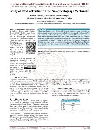
The research paper study the equivalent stress and shear stress generated on the pin due to friction between pin and links of a pantograph mechanism. The pin is subjected to biaxial loading of varying magnitude. The analysis comprises CAD model and simulated using a FEM solver. Materials of pin and links are selected considering real life applications and their coefficient of friction values are referred from variety of sources. Both static and dynamic coefficient of friction values are taken into consideration for analysis. Results thus obtained are tabulated and graphically demonstrated for better understanding of the outcomes. Chetan Rajoria | Ayush Johri | Harshit Nangia | Abhinav Goswami | Alok Shukla | Ajeet Kumar Yadav "Study of Effect of Friction on the Pin of Pantograph Mechanism" Published in International Journal of Trend in Scientific Research and Development (ijtsrd), ISSN: 2456-6470, Volume-3 | Issue-3 , April 2019, URL: https://www.ijtsrd.com/papers/ijtsrd23288.pdf Paper URL: https://www.ijtsrd.com/engineering/mechanical-engineering/23288/study-of-effect-of-friction-on-the-pin-of-pantograph-mechanism/chetan-rajoria<br>

E N D
International Journal of Trend in Scientific Research and Development (IJTSRD) Volume: 3 | Issue: 3 | Mar-Apr 2019 Available Online: www.ijtsrd.com e-ISSN: 2456 - 6470 Study of Effect of Friction on the Pin of Pantograph Mechanism Chetan Rajoria1, Ayush Johri2, Harshit Nangia2, Abhinav Goswami2, Alok Shukla2, Ajeet Kumar Yadav2 1SeniorAssistant Professor, 2Student 1,2Department of Mechanical Engineering, ABES Engineering College, Ghaziabad, Uttar Pradesh, India How to cite this paper: Chetan Rajoria | Ayush Johri | Harshit Nangia | Abhinav Goswami | Alok Shukla | Ajeet Kumar Yadav "Study of Effect of Friction on the Pin of Pantograph Mechanism" Published in International Journal of Trend in Scientific Research and Development (ijtsrd), ISSN: 2456- 6470, Volume-3 | Issue-3, April 2019, pp.1353-1356, URL: https://www.ijtsrd.c om/papers/ijtsrd23 288.pdf Copyright © 2019 by author(s) and International Journal of Trend in Scientific Research and Development Journal. This is an Open Access article distributed under the terms of the Creative Commons Attribution License (CC BY 4.0) (http://creativecommons.org/licenses/ by/4.0) I. INTRODUCTION Pantograph is a four bar mechanical linkage used to trace a motion and can scale it up or down. Widely used in railways and milling machines, this mechanism has a simple but very effective design. Problem generally faced in applying this mechanism into practical application includes reduced accuracy in tracing the figures. Reason for this is the enlarged values of stresses due to friction, inertia and gravity effects for bigger mechanism. Here, we have analyzed the effect of friction in terms of equivalent stress and shear stress. II. Literature Review S. K. Saha, Rajendra Prasad and Ananta K. Mandal [1] have built a compact, lightweight, easily operated, economic carpet cleaning machine utilizing a pantograph mechanism made to work along with Hoe ken’s mechanism. The machine is expected to ease the work of the carpet manufacturing labour and reduce the labour and production cost. Coyote Steel and Co. [2] handbook on steel sizes and weights provide a large tabulation of data for various steel bars of different cross sections and lengths. The geometrical ratios are very helpful in determining the size of the links of pantograph mechanism in CAD modeling. ABSTRACT The research paper study the equivalent stress and shear stress generated on the pin due to friction between pin and links of a pantograph mechanism. The pin is subjected to biaxial loading of varying magnitude. The analysis comprises CAD model and simulated using a FEM solver. Materials of pin and links are selected considering real life applications and their coefficient of friction values are referred from variety of sources. Both static and dynamic coefficient of friction values are taken into consideration for analysis. Results thus obtained are tabulated and graphically demonstrated for better understanding of the outcomes. KEYWORDS: pantograph mechanism, pin, links, coefficient of friction, equivalent stress, shear stress Engineers Handbook [3] is a website that provides value of coefficient of friction for different materials like aluminum, steel, copper, etc. This data is used throughout the simulation of the pin and links. III. Design of mechanism For the better understanding of the working of pantograph mechanism, a wooden model was constructed. A CAD modeled using SOLIDWORKS 2019 is generated. The dimensions of the links are given in Table. 1 Table.1: Dimensions of links Link Dimension* (mm) GD DT CF CE *all the dimensions are measured between hole centers IJTSRD23288 334.6 836.5 239 239 @ IJTSRD | Unique Paper ID – IJTSRD23288 | Volume – 3 | Issue – 3 | Mar-Apr 2019 Page: 1353
International Journal of Trend in Scientific Research and Development (IJTSRD) @ www.ijtsrd.com eISSN: 2456-6470 The arrangement of the links are shown in Fig.1 The links are made rigid to allow the entire load to transfer to the pin whereas pin is kept flexible to study the effects of friction on it. Fig.5: Link A, Link B and pin in assembly Fig.1: Link arrangement [1] IV. The materials selected for this application are Aluminum and Steel 4340. Aluminum and steel 4340 are most commonly available materials for construction of a machine. Their properties like toughness, high strength and fatigue strength, make them ideal for the analysis. The loading conditions are biaxial. A tangential load and a radial load with respect to the pin is applied on links A and B as shown in Fig.6. Links are simulated in four conditions with different load magnitude given in Table.3. Table.3: Loading Conditions Serial No. Tangential Load (N) Radial Load (N) 1 25 2 50 3 75 4 100 Material Selection and Loading The thickness of the links is taken as 9.525mm (3/8 in) [2] for the width of 50.8mm (2 in) shown in Fig.2 and Fig.3.The width of the link is taken after referring the handbook data [2]. To ease the simulation, only two links are made in SOLIDWORKS. These links are GD and DT named link A and link B respectively. 2.5 5.0 7.5 10.0 Fig.2: Link A Fig.6: loading on the links (ANSYS) These loading conditions are applied in two combination:- 1.Links-Aluminum, Pin:-Steel 4340 2.Links-Steel 4340, Pin:- Steel 4340 The shank of the pin is held fixed to mimic the fixed point of rotation of links. V. Simulation and results For solving the problem, ANSYS 19.2 is used. The assembly used is shown in Fig.7 is solved in Explicit Dynamics analysis system Fig.3: Link B Pin (Fig.4) used to join link A and link B is of dimensions given in Table.2 Table.2: Dimensions of pin Pin head diameter head thickness shank diameter shank length Dimension (mm) 44mm 5mm 30mm 19.05mm Fig.7: Assembly for final analysis Fig.4: Pin @ IJTSRD | Unique Paper ID - IJTSRD23288 | Volume – 3 | Issue – 3 | Mar-Apr 2019 Page: 1354
International Journal of Trend in Scientific Research and Development (IJTSRD) @ www.ijtsrd.com eISSN: 2456-6470 All the connections taken are frictional in behavior and such four frictional contacts are ?Between Link A and pin’s shank ?Between Link B and pin’s shank ?Between Link A and Link B ?Between Link B and bottom of pin’s head Fig.10: Shear stress on pin for 25N tangential load and 2.5N radial load Following the data obtained from Table.4, the variation of equivalent stress and shear stress with respect to load in shown in Fig11-13. Fig.8: Assembly after meshing I. For combination 1:- Links Pin Fixed entity Aluminum (Rigid) Steel 4340 (Flexible) Pin’s shank 1.05 for Aluminum- Aluminum contact 0.61 for Aluminum-Steel 4340 contact[3] 1.4 for Aluminum-Aluminum contact 0.42 for Aluminum-Steel 4340 contact[3] Coarse 1 sec 1e+05 Static coefficient of friction Dynamic coefficient of friction Meshing End time Number of cycles Fig.11: Maximum Equivalent stress vs load Data thus obtained is in Table.4 Table.4: Equivalent stress (Pa) Shear stress (Pa) Load (N) Tangenti al Radia l Max Min Max Min - 1.80e 7 4610 8 2.18e 6 25 2.5 9.45e 6 - 3.37e 6 - 1.33e 7 - 4.88e 7 9.05e 6 1179 9 1.27e 6 50 5.0 2.48e 7 1904 3 2.42e 6 75 7.5 Fig.12: Minimum Equivalent stress vs load 8.68e 7 1.47e 5 8.55e 6 100 10 Fig.9: Equivalent stress on pin for 25N tangential load and 2.5N radial load Fig.13: Shear stress vs load @ IJTSRD | Unique Paper ID - IJTSRD23288 | Volume – 3 | Issue – 3 | Mar-Apr 2019 Page: 1355
International Journal of Trend in Scientific Research and Development (IJTSRD) @ www.ijtsrd.com eISSN: 2456-6470 II. For combination 2:- Links Pin Fixed entity Static coefficient of friction Dynamic coefficient of friction Meshing End time Number of cycles Steel 4340 (Rigid) Steel 4340 (Flexible) Pin’s shank 0.78 for Steel 4340- Steel 4340 contact [3] 0.42 for Steel 4340- Steel 4340 contact [3] Coarse 1 sec 1e+05 Fig.17: Minimum Equivalent stress vs load Data thus obtained is in Table.5 Table.5: Equivalent stress (Pa) Shear stress (Pa) Load (N) Tange ntial 25 50 75 100 Radial Max Min Max Min 2.5 5.0 7.5 10 2.68e6 3.44e6 4.25e6 9.27e6 3471.9 2.47e5 6799.5 1.08e5 5241 3.4e4 -1.39e6 -1.87e6 -2.2e6 -4.73e6 5.3e5 1.06e6 Fig.18: Shear stress vs load VI. From the obtained data, we can see that for combination 1, the values of equivalent stress and maximum shear stress at 50N tangential load, 5N radial load is minimum, and highest value of minimum shear stress is obtained here. For combination 2, at 75N tangential load and 7.5N radial load, only minimum equivalent stress shows a deviation from general trend of increment. VII. Conclusion ?From obtained data we can tell that under same loading conditions, Steel 4340 shows less equivalent stress and shear stress at pin hence much better for construction ?Equivalent stress and maximum shear stress curves for Aluminum-Aluminum combination has an inverted bell shape and upright bell shape for minimum shear stress ?Steel 4340-Steel 4340 shows continuously increasing trend in maximum equivalent stress and maximum shear stress. ?The value of minimum equivalent stress for Steel 4340- Steel 4340 experiences a reduction References [1]Saha, S. K., Prasad, R., & Mandal, A. K. (2003). Use of Hoeken’s and Pantograph mechanisms for carpet scraping operations. In Proceedings of the 11th National Conference on Machines and Mechanisms (pp. 18-19). Observations Fig.14: Equivalent stress on pin for 50N tangential load and 5N radial load Fig.15: Shear stress on pin for 50N tangential load and 5N radial load Following the data obtained from Table.5, the variation of equivalent stress and shear stress with respect to load in shown in Fig16-18. [2]Coyote Steel & Co. 2030 Cross Street Eugene, Oregon 97402 USA No.1 Handbook of STEEL SIZES & WEIGHTS for Industry, copyright 2001 [3]Reference table of coefficient of friction. (n.d.). Retrieved http://www.engineershandbook.com/Tables/frictionc oefficients.htm from Fig.16: Maximum Equivalent stress vs load @ IJTSRD | Unique Paper ID - IJTSRD23288 | Volume – 3 | Issue – 3 | Mar-Apr 2019 Page: 1356