SPECIFICATIONS, CONCEPT GENERATION AND SELECTION SUMMARY
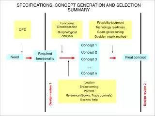
SPECIFICATIONS, CONCEPT GENERATION AND SELECTION SUMMARY. QFD. Functional Decomposition Morphological Analysis. Feasibility judgment Technology readiness Go/no go screening Decision matrix method. Ideation Brainstorming Patents Reference ( Books , Trade Journals ) Experts ’ h elp.

SPECIFICATIONS, CONCEPT GENERATION AND SELECTION SUMMARY
E N D
Presentation Transcript
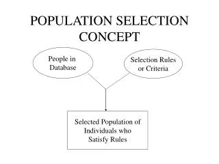
SPECIFICATIONS, CONCEPT GENERATION AND SELECTION SUMMARY QFD Functional Decomposition Morphological Analysis Feasibility judgment Technology readiness Go/no go screening Decision matrix method Ideation Brainstorming Patents Reference (Books, Trade Journals) Experts’help Concept 1 Concept 2 Concept 3 … Concept n Required functionality Final concept Need Design review 1 Design review 2
IT IS TIME TO START THE NEXT DESIGN PHASE: THE DETAILED DESIGN • Specification Development / Planning Phase Determine need, customer and engineering requirements Develop a project plan • Conceptual Design Phase Generate and evaluate concepts Select best solution • Detail Design Phase Documentation and part specification Prototype evaluation • Production Phase Component manufacture and assembly Plant facilities / capabilities • Service Phase Installation, use , maintenance and safety • Product Retirement Phase Length of use, disposal, and recycle
WE NOW NEED A NEW TOOL: CAD Quality function deployment Gantt’s charts Critical path method Ideation Brainstorming Patents Reference materials Functional decomposition and morphological analysis Sketches Feasibility judgment technology readiness assessment Go/no-go screening Decision matrix method (with pair-wise comparison) CAD Specification Development / Planning Phase Conceptual Design Phase Concept generation Conceptual Design Phase Concept selection Detailed Design Phase
EVOLUTION OF CAD TOOLS 1970’s Manual drafting Electronic drafting board 1980’s Wire frame geometry Surface geometry 1990’s Solid geometry
MODERN CAE TOOLS COMPUTATIONAL FLUID DYNAMICS FINITE ELEMENT ANALYSIS CAD SOLID, PARAMETRIC, FEATURE BASED ….. MOTION ANALYSIS ….. Computer Aided Design (CAD) is at the hub of other Computer Aided Engineering (CAE ) tools
IN MME2259a WE USE SolidWorks CAD SOFTWARE You can burn your installation DVD on any lab computer
WHAT IS A SOLID, PARAMETRIC, FEATURE BASED CAD? PARAMETER SOLID GEOMETRY BASE FEATURE (“POSITIVE” SOLID) CHILD OF BASE FEATURE (“NEGATIVE” SOLID) panel 01.SLDPRT
TO TAKE FULL ADVANTAGE OF A SOLID, PARAMETRIC, FEATURE BASED CAD WE NEED TO UNDERSTAND HOW TO USE IT. • WE’LL SPLIT OUR REVIEW INTO: • MODELING PHILOSOPHY • SKETCHES • FEATURES • PARTS • ASSEMBLIES • DRAWINGS
MODELING PHILOSOPHY There is one factor of model building philosophy which stands above others – what matters the most is what we want to do with the final geometry. Model geometry is not created to stay – it is meant to be changed. We need to understand which features we would like to drive and control some other ones, what portions are to be modified, what are the boundaries of modifications; and anticipate how the model is going to be developed further. All of this has to be incorporated in the model history and developed to a state where the model “behaves” the intended way. We call this The Design Intent.
MODELING PHILOSOPHY The objective is not only to arrive to the destination – build the final geometry – but to walk the journey towards it. Road to the destination will teach us the reasons why and after arriving to the destination we will start to understand. There are no shortcuts or quick leaps there. How does this all reflect on the model building techniques? The model has to be able to easily handle changes down the road (and, for sure, there will be changes). Changing basic dimensions, changing number of features, changing shape – the model should handle all such requests.
MODELING PHILOSOPHY 3D solid modeling software usually creates 3D geometry by taking a 2D sketch and extruding, revolving, sweeping and blending it in a “third“ direction which results in a 3D feature. Both the sketch and the feature are parametric – dimension driven. Changing the values of dimensions (if they are meaningful) forces the geometry to assume new shape.
MODELING PHILOSOPHY Proper feature geometry starts with proper parametric sketch. Sketch is the entry point to incorporate design intent in the model. Each 2D sketched entity will become a portion of a 3D feature, e.g. lines will be converted to surfaces, endpoints become edges, circles will become cylinders, etc. 90% of all errors are errors in sketches!
MODELING PHILOSOPHY The way that geometry is built does not necessarily reflect manufacturing process of a real, physical part. It rather resembles a step-by-step approach by adding and subtracting material. For example, while in real life a machined part is created always by removing material only, 3D modeling combines solid protrusions (adding) and cuts (removing) to build geometry. This is why the dimensioning scheme on model cannot effectively replicate manufacturing dimensioning scheme.
SKETCHES Sketch can be placed on a reference place or a flat face of already existing geometry. If possible, use underlying geometry to position sketch entities
SKETCHES Construct the first sketch on the first reference plane Extrude in positive direction Keep sketches simple Use sketch relations where possible Test relations by rebuilding sketch with different dimensions Constrain all sketches Give sketches some meaningful names
SKETCHES Sketch should not contain more than 12-15 geometric entities (lines, arcs, conics, etc.) included construction geometry (centerlines, sketched points). The more complex the sketch the harder is to control it with minimum number of dimensions. Less is more. Sketch implicit rules (assumptions or constraints) should be maximized to simplify the geometry. Abundance of dimensions is worst than their scarcity. The more dimensions we have to drive a sketch, the easier it is to omit one when modifying feature geometry. This is one of the most frequent mistakes.
SKETCHES No symmetry relations With symmetry relations Use relations in sketches plate 001.prt
SKETCHES Use relations in sketches plate 001.prt
SKETCHES sketch extrusion pattern Use construction geometry to create “intelligent” sketches. Here we want to control the bolt circle diameter of three holes placed in 120º. increments about the center axis of a flange. flange.prt
SKETCHES Use underlying parent features for proper alignments of sketches. This will create parent-child relationship between features. Use consciously for controlling children through parents “Massage” the sketch – change values of crucial dimensions and update it to find out if it behaves the way you like. flange.prt
SKETCHES Exaggerate the sketch when creating features. Say we would like to sketch a line 1º. from vertical. It is easier to sketch it about 10º from vertical, dimension it and modify the dimension to 1 deg, than try to sketch it almost vertical, dimension it and expect the system to accept the value. The system’s implicit rules will kick-in assuming the line should be vertical and we will have hard time to overrule it.
SKETCHES YES NO Add details to features, not to sketches (also see the next slide) cup.prt
SKETCHES BASE FEATURE FILLET FEATURE cup.prt
FEATURES Main geometry Half detail Detail • Create main geometry • This is usually the main volume - the biggest feature, although it does not have to be. This feature becomes parent to majority of following features. • Add half-detail • These will be features like shells, construction ribs, cutouts, etc. • Finally create fine detail • These features are usually pick-and-place features such as rounds, chamfers, drafts, cosmetic grooves, etc. plate with boss.prt
FEATURES Cosmetic feature Cosmetic feature YES NO When creating features avoid undesirable parent-child relationships. Features representing “cosmetic” (fine detail) geometry should not be parent of any subsequent features, unless driven by design intent plate with boss.prt
FEATURES YES Sketch on reference plane NO Sketch on face When orienting the sketch use construction planes, rather than solid features in case the solid feature will be later redefined and its children fail by losing their references. pipes.prt
FEATURES Axis of rotation Sketch When creating features of one kind (e.g. revolved), use the same construction plane for sketching and orientation. Sketch the entities always on the same side of the centerline of rotation (e.g. left-hand) pipes.prt
FEATURES NO Avoid unattached geometry (two or more solid bodies within part). The part geometry is by definition a continuum and should remain continuum anytime during the history of feature creation. pipes.prt
PARTS All part features should be unsuppressed when releasing (making the final version) the part. Part must have material property and color assigned Part must not be in roll-back mode Features and sketches must be named All sketched must be fully defined Use mm, N, s, K units ( important for analysis) Zoom to fit and position in isometric view before saving
ASSEMBLIES Assembly of 3D solid modeling software in general does not contain “assembly” geometry. The assembly contains components (i.e. parts and lower level assemblies) assembled together in the intended manner. Assembly contains information on where to find parts and how are parts oriented relative to each other (mated). The only features that can be defined in assembly are “negative” features (cut)
ASSEMBLIES When retrieving the assembly (opening assembly file), CAD program needs the following information: - BOM (Bill of Material) structure: This information is stored within assembly file and is used to retrieve all listed components. It is obvious, that the system has to be able to “see” and retrieve all components regardless where they reside on the network. - “Mating” information: How feature surfaces of individual components are assembled - mated to their parent components. - Feature information: Assembly cuts (in case they have been created) and parts/features that are being intersected by them.
ASSEMBLIES BOM MATING INFO ASSEMBLY FEATURE (CUT) shear pin.sldasm
ASSEMBLIES Mating can use parts geometry or reference geometry bracket002.sldasm