WAN Technologies
WAN Technologies. Chapter Topics. Introduction to Wide-Area Networking WAN technologies. What Is a WAN?. WANs encompass broad geographical areas You typically do not own the WAN costs involved are too high Network providers most often supply connections through their systems

WAN Technologies
E N D
Presentation Transcript
Chapter Topics • Introduction to Wide-Area Networking • WAN technologies
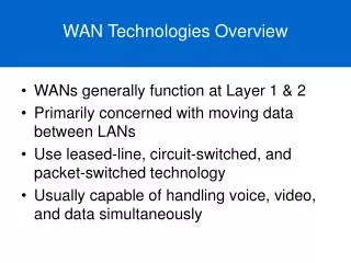
What Is a WAN? • WANs encompass broad geographical areas • You typically do not own the WAN • costs involved are too high • Network providers most often supply connections through their systems • Can even provide portions of the hardware required
What Is a WAN? • Network providers charge fees, or tariffs, for use of the WAN • Circuit-switched environments often use time of active connection • Leased-line environments frequently use an amount that considers access bandwidth and distance
What is a WAN? • WAN technologies operate at the lowest three layers of the OSI model
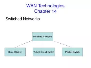
WAN Categories • We divide WAN technologies into categories that help define their nature • Leased lines • Circuit-switched • Packet-switched • Cell-switched
Leased Lines • Refered to as point-to-point links • Typically more reliable and more expensive when compared to the other WAN categories • completely reserved for transmissions and they are always available
Leased Lines • SP’s reserve an entire physical circuit from the network access point to the customer premises • Circuit might be over-dedicated physical media or a channel maintained using frequency modulation (FM) or time-division multiplexing (TDM) • Synchronous serial connections are common examples of leased lines
Circuit-Switched Lines • Classic example is a telephone call over the PSTN • Call establishes a connection between the two end points and then terminates (or tears down) this connection when communications complete
Circuit-Switched Lines • WAN equipment dedicates a physical path to the communications while they are occurring • No other participants can use the physical medium while communications continue • Examples of circuit-switched WAN technologies include ISDN and asynchronous serial connections
Packet-Switched Lines • Typically reduce costs to the organization • service provider experiences a more efficient use of its equipment • efficiency is a result of customers sharing the WAN resources
Packet-Switched Lines • Network equipment creates “virtual circuits” through the shared WAN provider’s network • Virtual circuits (VCs) transport the data (segmented as packets) through the WAN • Circuits are typically permanent (PVCs) or switched (SVCs)
Packet-Switched Lines • SVCs tend to have a lower cost • are appropriate when users transfer data sporadically over the WAN • network equipment builds connections on demand as needed • connections terminate when transmission completes
Packet-Switched Lines • PVCs are permanently established connections • more appropriate for WAN environments where constant data transfers occur • PVCs tend to be more expensive • often guarantee bandwidth availability • no overhead required with establishing connections, transferring data, and terminating connections, as with SVCs
Cell Switching • Network divides data into units of a fixed size called cells • Provider can transmit these fixed size cells efficiently over a physical medium • ATM
WANs and the Enterprise Composite Network Model • WANs operate between the Enterprise Edge and the SP Edge using the various technologies in this chapter.
WAN Technologies • There are many technologies available for designing WAN infrastructures • You should acquire a solid comprehension of the technology options available before designing WAN solutions
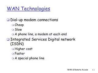
Dial-Up • Refers to the use of a modem connected to the PSTN to carry data • Available bandwidth is lowest with this technology • 53 Kbps with current V.90 standards
Dial-Up • Still a popular remote-access choice for home office and telecommuters • Low costs and almost universal availability • inexpensive customer premises equipment • Have managed a presence in more than just the home-office environment • dial-on-demand routing (DDR) capabilities built in to most Cisco devices • Another reason why dial-up solutions continue to appear • WAN backup options
ISDN • ISDN permits the digitization of access to the telephone network • existing phone lines are capable of carrying data in a digital form
ISDN • Important that network designers understand the devices and reference points • ISDN terminals that are “ISDN ready” are terminal equipment type 1 (TE1s) • Non-ISDN terminals are TE2s • To connect a TE2 device to the ISDN network, use a terminal adapter (TA)
ISDN - Devices • TE1 and TE2 devices connect to network termination type 1 (NT1) or network termination type 2 (NT2) devices
ISDN - Devices • NT1 and NT2 devices connect the four-wire subscriber wiring to the two-wire local loop provider network • In North America, the NT1 is a customer-provided CPE device • most other parts of the world, this device is part of the carrier’s network • NT2s are more complicated devices usually found as components in PBXs • They typically provide Layer 2 and 3 protocol functions and concentration services.
ISDN Reference Points • R reference point identifies the area between non-ISDN equipment and the TA • S reference point identifies the area between user terminals and the NT2 • T reference point identifies the area between the NT1 and NT2 devices
ISDN Reference Points • U reference point identifies the area between the NT1 devices and line-termination equipment in the carrier network • U reference point is relevant only to ISDN subscribers in North America
Basic Rate Interface • offers two bearer (B) channels and a single delta (D) channel • B channels transmit data and operate at 64 Kbps • D channel handles signaling and operates at 16 Kbps • BRI also provides for framing control and other overhead, thus bringing the total bit rate to 192 Kbps
Primary Rate Interface • In North America and Japan • PRI ISDN over T1 media provides 23 B channels and 1 D channel • D channel operates at 64 Kbps • Total bit rate to 1.544 Mbps • In Europe, Australia, and other parts of the world • PRI is provisioned over E1 with 30 B channels and 1 D channel • D channel operates at 64 Kbps • Total bit rate of 2.048 Mbps
X.25 • An ITU-T WAN protocol • Mainly a legacy WAN technology • Designed to operate over links with Relatively high bit-error rates • Features high overhead due to built-in error detection • Frame Relay, leaves such error recovery to upper layers of the OSI
X.25 • X.25 WAN devices include • Data terminal equipment (DTE) • end systems - your workstations or other network hosts • Data circuit-terminating equipment (DCE) • generally located in the carrier’s facilities • Packet-switching exchange (PSE) • witches that compose the bulk of the carrier’s network • transfer data from one DTE device to another through the X.25 PSN
X.25 • Another common device - packet assembler/disassembler (PAD) • X.25 relies upon PADs when an end device cannot implement the full X.25 functionality • PAD is located between the end device and a DCE device • PAD performs three primary functions • Buffering • Packet assembly • Packet disassembly.
X.25 • Maps to the lowest three layers of the OSI reference model • Use the following protocols: Packet-Layer Protocol (PLP); Link Access Procedure, Balanced (LAPB) • Variety of physical-layer protocols (such as EIA/TIA-232, EIA/TIA-449, EIA/TIA-530, and G.703)
X.25 • Supports both SVCs and PVCs • PVCs are more common with Frame Relay, SVCs are more common with X.25 • X.25 requires special addressing • uses X.121 addresses in call setup mode to establish SVCs
Frame Relay • Considered by many to be a streamlined version of X.25 • Does not involve the intense error recovery that occurs with X.25 • operations to the lower two layers • allows higher-level protocols to concern themselves with transmission errors • Originally intended for use across ISDN interfaces • Occurs over a variety of other network interfaces as well
Frame Relay • Frame Relay networks rely upon • DCE and DTE devices • virtual circuits for the transmission of data • can be SVCs or PVCs • PVCs are more common
Frame Relay • Frame Relay uses data-link connection identifiers (DLCIs) • service providers typically assign these values • have only local significance • values are unique in the LAN but not necessarily in the Frame Relay WAN • Implements simple congestion-notification mechanisms • forward-explicit congestion notifications (FECNs) • backward-explicit congestion notifications (BECNs)
Frame Relay • Also uses a Discard Eligibility (DE) bit • Indicate that a frame has a greater probability of loss by discard than other frames • frame has lower importance than other frames • Will be dropped first if congestion is noticed
Local Management Interface • A set of enhancements to the basic Frame Relay specification • Created by the Gang of Four in 1990 • Cisco Systems, StrataCom, Northern Telecom, and Digital Equipment Corporation • offers a number of features (called extensions) for managing complex internetworks • global addressing, virtual-circuit status messages, and multicasting
SMDS • High-speed, packet-switched, datagram-based WAN technology used for communication over public data networks (PDNs) • Uses fiber- or copper-based media • Speeds of • 1.544 Mbps over Digital Signal Level 1 (DS-1) transmission facilities • 44.736 Mbps over Digital Signal Level 3 (DS-3) transmission facilities
SMDS • Data units are large enough to encapsulate entire IEEE 802.3, IEEE 802.5, and Fiber Distributed Data Interface (FDDI) frames • Network consists of several underlying devices to provide high-speed data service • include CPE, carrier equipment, and the subscriber network interface (SNI)
SMDS • CPE is terminal equipment typically owned and maintained by the customer • CPE includes end devices, such as terminals and personal computers, and intermediate nodes, such as routers, modems, and multiplexers • Carrier equipment generally consists of high-speed WAN switches • SNI is the interface between the CPE and carrier equipment
SMDS • Uses the SMDS Interface Protocol (SIP) for communications between CPE and SMDS carrier equipment • provides connectionless service across the SNI, allowing the CPE to access the SMDS network • Derives its origins from the IEEE 802.6 Distributed Queue Dual Bus (DQDB) standard • Cell relay across metropolitan-area networks (MANs)
SMDS • Protocol data units (PDUs) carry both a source and a destination address • Addresses are 10-digit values resembling conventional telephone numbers • Offers group addressing and security features • A single address can refer to multiple CPE stations • Analogous to multicasting on LANs
SMDS • Two security features • Source-address validation • ensures that the PDU source address is legitimate and represents the true SNI from which it originated • Prevents address spoofing • Address screening • allows a subscriber to establish a private virtual network that excludes unwanted traffic
Asynchronous Transfer Mode • An ITU-T standard for cell relay • Developed to provide converged services for voice, video, and data • Transmits information in small, fixed size cells • Networks are connection-oriented
Asynchronous Transfer Mode • Cell-switching and multiplexing technology • Combines the benefits of circuit switching (guaranteed capacity and constant transmission delay) with those of packet switching (flexibility and efficiency for intermittent traffic) • Provides scalable bandwidth from a few megabits per second (Mbps) to many gigabits per second (Gbps)
ATM Cells • Cells consist of 53 octets, or bytes • First 5 bytes contain cell-header information, and the remaining 48 contain the payload (user information) • Small, fixed-length cells are well suited to transferring voice and video traffic
ATM Networks • Consists of a set of ATM switches interconnected by point-to-point ATM links or interfaces • Switches support two primary types of interfaces • User-Network Interface (UNI) • Connects an ATM end system (such as hosts and routers) and a private ATM switch or a private ATM switch and the public-carrier ATM network switch node. • Network Node Interface (NNI) • Connects two network nodes
ATM Networks • Networks are connection-oriented • A virtual channel (VC) exists across the ATM network prior to any data transfer • Channel is much like a virtual circuit