DESpec
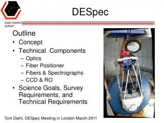
DESpec. Outline Concept Technical Components Optics Fiber Positioner Fibers & Spectrographs CCD & RO Science Goals, Survey Requirements, and Technical Requirements. Tom Diehl, DESpec Meeting in London March 2011. Acknowledgements.

DESpec
E N D
Presentation Transcript
DESpec Outline • Concept • Technical Components • Optics • Fiber Positioner • Fibers & Spectrographs • CCD & RO • Science Goals, Survey Requirements, and Technical Requirements Tom Diehl, DESpec Meeting in London March 2011
Acknowledgements • Darren DePoy, Steve Kent, Brenna Flaugher, Rich Kron, Tim Abbott, Jennifer Marshall, J.-P Rheault • Risa Wechsler, Heidi Wu, Brian Gerke, Will Percival, Lado Samushia, Ofer Lahav, Josh Frieman, Julia Campa, Jiangang Hao • Matthew Colless, Guy Monnet, Rob Sharp, Scott Croom, Karl Glazebrook • Michael Seiffert
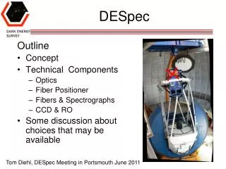
DECam => the Blanco Telescope @ CTIO Filters Shutter CCD Readout Cage Cartoon from June 2008 5 Optical Lenses Hexapod For alignment & focus
DESpec Concept • An idea to make a significant impact on the understanding of dark energy • Build an instrument to perform spectroscopic follow-up of targets identified in DES data, taking advantage of the DECam strengths (red-sensitivity). • An instrument that could be inter-changeable with DECam in a reasonably short time is desired. • An instrument that can be built at about the same cost and schedule as DECam (ready by the end of DES) is desired.
Main Technical Challenges Not particularly ordered by difficulty, risk, WBS, or amount of R&D … • Optics • Focal Plane and Fiber Positioner • Spectrographs and Fibers • CCDs & Readout
Estimate of Sensitivity DePoy • Redshift determinations could be made using • Absorption lines (takes longest) assumed this below • Emission lines for some galaxies (faster) • Throughput & Sensitivity • DECam gets us 600 photons per second from a mag 20 source in a broadband filter (Dl/l~0.2). • The Dl/l for 150 km/s is ~0.0005 (R~2000), so mag 22.5 (20) has 0.075 (0.75) photons/sec in a resolution bin (assuming 50% throughput relative to DECam). • Taking into account the brightness of the dark sky, and using ~1 arcsec fibers (~60 microns), the S/N is ~0.087 * T**0.5 for mag 22.5 source. • Requires an hour for S/N of 5 for mag 22.5 (faint) galaxy.
# Fibers vs. # Nights • There are roughly 50M mag < 22.5 galaxies in 5000 sq-deg and there are ~2.5x that per magnitude. • It is possibleto arrange~4000 fiberpositionersonthe DECam focal plane using an 0.7 cm pitch. • For example: 1000 nights, 8 setupsper night, and F=0.7 yields ~22M 1-hr spectra. 4-5esposures per “tile”. • Or: 2630 exposures over 110 nights and eff’t of 75% for E.L.G. => 5.5M targets • Intelligent algorithms, which maximize the number of observed objects, result in ahigheryield.
DESpecOptics This work was done by Steve Kent • Reuse the DECam optics (focal ratio f/2.9) • The DECam Dewar needs its window (C5) as the cover, providing opportunity to use a new optical window for DESpec. Move it a little closer to the nominal FP because of ADC. • The DESpec optics require an atmospheric dispersion corrector to remove the prismatic effect of the atmosphere. There is space (236 mm) in the F-C.S. slot for this plus the shutter. FP FoV has Radius = 225.54 mm
Spot Size S.KentAug. 2010 • Good spot size for 550 < l < 1080 nm • The achromatic DECam optical design won’t allow both the blue side and the red side intoaspectrum. • At zenith angle = 55 deg (though it’s independent of ZA) • The ADC works • The best focus (FWHM) is at the center and is 0.4”. • The worst is at the edge, where the FWHM is 0.9” (~50 microns). SK calls this “lateral chromatic”.
Spot Size [2] ADC Variant S.Kent Nov. 2010 • Improved performance by putting some slight curvature into the first and last surfaces of the ADCs. • Still maintains good focus (FWHM) at the center and is 0.4”. • The worst is still at the edge, where the FWHM is 0.63” (~34 microns).
Atmospheric Dispersion CompensatorExample • The WYIN ADC has diameter 635 mm. The prisms are rotated using a pair of encoded stepper motors. • Two prisms each made from two wedge-shaped pieces of different glass materials. • Issues include optical alignment and position (movement) tolerance and backlash • Cementing the pieces together must be done “nicely”.
Filter-Changer/Shutter Slot • The slot is 900 mm tall and 236 mm wide. See DECam drawing 436803. • The shutter is 55 mm wide, not including thebolt heads.
Almost Telecentric Small deviation from normal incidence at outer radius • The focal plane is almost but not quite telecentric (3.8 deg tilt at the edge, 0 deg at center) • At nominal F/2.9 the convergence angle of the light is 19.7 deg center (20.9 deg @ edge). • Typical fibers can accept light in 25 deg cone • To get optimal performance one could tilt the fibers out as they go out in radius (SDSS) otherwise some light loss. Steve Kent. Oct. 2010
Fiber Positioners • Typical Specifications • Premium on small (7 mm) spacing between actuators (pitch) • ± 0.14” (± 1/2 pixel on DECam) position accuracy corresponds to ±7.5 um. • 60” target separation is ~3.2 mm spacing between fiber tips • Fast reconfiguration time: 5 minutes or less • Targeting efficiency! • Maximum throughput, highly reliable … • There are plenty of well-developed concepts and operating examples: twirling posts (WFMOS & Lamost), Spines (Echidna), Pick & Place fibers (AAW), Plug Plates (SDSS) • And some novel devices in R&D: StarBugs
Plug Plate • Plates are prepared in advance by drilling holes in the imaged locations of targets • A person plugs fibers from a harness into the plate and an illumination trick is used to determine which fiber is in which hole • A plate is useful only for one configuration
Example “Twirling Post” • Here, a FP with 2400 “Cobras”, a “twirling post” with a rotating fiber. Two axes of rotation M. Seiffert (JPL) presentation at P.U. 11/09 WFMOS “Cobra” Fiber Patrol Radius
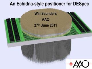
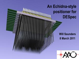
Example “Spines” • Echidna: an Australian marsupial with flexible spines • Also an operating fiber-positioner from AAT with ~400 fibers. • Spines pivot from mounts near the bases • Naturally handles a varying target density because the tips are small • <~10 minute configuration time FMOS Echidna on the Subaru Also was a wfmos proto
Echidna Spine • 7 mm pitch is available • Adjustable length about 16 cm • Patrol radius ~ 7 mm • Positioning accuracy < 10 microns is already achieved • Improved configuration time. • <5 minute configuration time set mainly by the amount of time it takes to scan a camera over the face of the array and measure position of fiber tips Picture from Graham Murray (Durham)
Example Pick & Place Robot • AAW is a 492-fiber spectograph at Prime Focus of AAT • A robot picks up each fiber and places on the FP. • Looks like there is a 45 deg mirror on the end of each fiber. • Takes a long time to configure a plate. • They use two plates, observe on one, configure the next
Example StarBugs • Magnetic buttons secure a “walking” robot that carries a fiber on the FP. • Lift & step motion, footprint < 10 mm. Can even vary payloads. • Fast configuration. All fibers can move at the same time w/ speed ~1 mm/s. • Relatively cheap. Can work on a curved FP (not one of our problems) • Probably limited to 1000 to 1500 on our FP at this time with sep. > 180”
Some Comparisons • Plug Plates are more costly but less technical risk • Pick and Place Robots cannot be scaled up past about 500 fibers in a cramped focal plane due to fiber crossover and space problems • Starbugs needs R&D to make them smaller. Present size allows 1000 to 1500 on the Focal Plane (FP). • Twirling Posts need R&D to make them smaller. Present size allows 1000 to 1500 fibers on the FP. I believe the R&D is ongoing. • Echidna-like spines will allow ~4000 fibers on the FP • R&D would better quantify light-loss at the edge of the FP, fiber density, and controls software to minimize configuration time.
More Fiber Positioner Components • Fiber Positioner Support Plate or module • Control Electronics • Guide and Focus CCDs and algorithm • Camera to measure the present fiber position during configuration - backlight the fibers and a backup system (Roger S.) • These should not be ignored as we move to better specify the design LAMOST
Spectrographs & Fibers • F/3 is ideal for injecting light into low-cost high-efficiency fibers (see Fig below-right) & will present minimal FRD (Murphy et al., SPIE 2008) • An inexpensive F/3 example is the 1-arm VIRUS, being mass-produced by Texas A&M for HET or the MUSE for VLT. • Each spectrograph will handle ~200 fibers. Need about 20 spect’s. • R&D needed for trades & tests with prototypes • Ideas: more resolution, 1-arm vs 2-arm spectrographs, 2 different resolutions, separate fibers for green & red bands, … need science definition Ramsey (1988)
Example: VIRUS Spectrograph Jennifer Marshall will talk about these in more detail Hill et al. (2006) • Compact, inexpensive, high throughput optics. • Holographic disperser (VPH) • R~1000 VIRUS Optics. Linear array of Fibers is out of page.
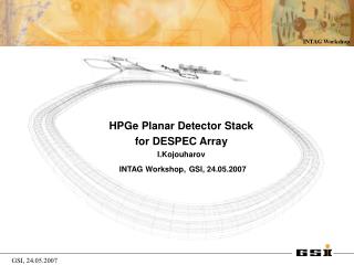
CCDs & R.O. LBNL CCD has high red response • The red-sensitivity of the imaging survey suggests we use DECam-like CCD’s • Arrange the spectrum along the long axis of the 2kx4k device, R~2000. • The number of systems (~20) depends on # fibers per spectrograph. • CCD & Read Out electronics seem straightforward. The DECam CCD & R.O. would work well for this. • At 100kpix/s we could have 2 to 2.5 electrons RO noise • We are doing R&D to take that to < 1 e- but not needed here?
Interchangeable w/ DECam • To install DESPec 1st stow DECam off-telescope • We are providing hardware to install/remove DECam as part of that project (see right) • Then pick up DESpec, and using similar hardware, install it on the end of the barrel. • In reverse, either store DESpec on the telescope or produce a convenient way to connect/disconnect the fibers. • We bring this into the design ab initio so that the process can be done quickly and easily.
Connection Between Design Concepts and Requirements • It has been useful to us to maintain basic feasibility and demonstrate it through examples. • We haven’t made any technical choices, though we have some assumptions that we are holding (loosely) as constraints. • In early development of the idea we want to explore the scope of technical possibilities and to provide feedback to the development of the science case. • We will have to document how the technical requirements are based on the survey and science requirements • and describe how technical risk effects the probability of meeting the science goals.
Survey Reference Design • Technical Requirements • Optics • DECam Corrector (3.8 sq-deg) with freedom at C5 • Requires an A.D.C. • Fiber Positioner • 4000 fibers • <~5 minutes/configuration • 7 micron pointing accuracy • Various components • Weight limit? • Spectrographs • 1-arm, Red-sensitive CCD • 200 fibers per CCD • R~2000 • CCD & RO Survey Requirements • Mag <22.5 w/ S/N > 5 (R~2000) in 60 minutes or less • Wavelength Range • 550<l<1080 • Fiber Positioner • 22M targets • Spectrographs (lower R to higher R) Need to specify • 150 km/sec resolution => masses for some LRGs • S/N for weak emission lines • Separate OH lines for good sky-subtraction • O2 emission line separation
Summary • Technical Challenges but No Show Stoppers! • DES Optics limit the wavelength to ~550 to 1080 nm.We need an ADC. • A fiber positioner is a very complex machine. Multiple options include “twirling posts”, flexible spines (like small marsupials), and little walking R2D2’s. There are trade-offs. • Spectrograph, CCD, and Readout seem straightforward. • I’ve mentioned three kinds of requirements here: science requirements, survey requirements, and technical requirements. Possibly also constraints.
Table • Dlam/lam=.5*(4000)*15microns*/(2F*1.5/um)= • 1080-550=530 nm range with 815 in middle • ~1000 resolution elements • Dl/l = .53/530
FRD & Throughput vs. F Ratio • Tested focal ratio degradation and throughput vs input focal ratio and output focal ratio for various diameter fibers. • Bigger fibers => more throughput. • Concludes F/3 to F/4 is ideal. F/3 F. Ramsey, “Focal ratio degradation in optical fibers of astronomical interest” , Proceedings of the Conference Fiber Optics in Astronomy, 1988.
Spectrograph Throughput Hill et al. (2004) • 18% Includes everything, the whole system, including the sky • e(fiber)=0.68 to 0.88 • e(atmosphere and telescope) = 0.3 to 0.5 • e(CCD&Spectrograph) = 0.25 to 0.40 • Start with T = 0.18. Dividing out the atmosphere factor and using an LBL CCD takes our throughput to >50% relative to DECam.
Fiber Alternative Decision Tree M. Seiffert (JPL) presentation at P.U. 11/09
References • A. E. Evrard et al., Astrophys.J.672:122-137,2008. • M. White, J.D. Cohn, and R. Smit, to be published in MNRAS (2010). Arxiv/1005.3022. • R. E. Angulo et al., MNRAS 383, 755 (2008) • L. Ramsey, Proceedings of the Conference Fiber Optics in Astronomy, Tucson, AZ Apr. 11-14,1988. • J.D. Murphy et al., Proc. SPIE Vol. 7018, 70182T (2008). • J.G. Hill et al., Proc. SPIE Vol. 5492, 251 (2004). • J.G. Hill et al., Proc. SPIE Vol. 6269, 93 (2006).