Download

1 / 33
330 likes | 455 Vues
Hand Held Products 2.4GHz Site Survey. Table of Contents. Survey Preparation. Survey Tools. Problem Sources. Antenna Technology. Performing the Survey. Documentation. Performing An Effective Site Survey. 2. Elevator. Take Inventory. Optional. Required. Two blueprints.

E N D
Hand Held Products 2.4GHz Site Survey
Table of Contents Survey Preparation Survey Tools Problem Sources Antenna Technology Performing the Survey Documentation
Performing An Effective Site Survey 2 Elevator
Take Inventory • Optional Required Two blueprints Distance measuring device (i.e., tape measure) Different Colored Markers RangeLAN2 Master unit 150’ power cord Laptop with a RangeLAN2 PC Card Location markers (i.e., chalk, or colored tape) Notepad Duct tape for mounting antenna Spare Batteries (Lap Top) Antennas
Before the Survey Identify minimum pkt size acceptable for application Note ALL areas where coverage is needed Use color codes to represent radio hazards (i.e., metal walls, cement) Identify potential interference, both environmental and radio Determine number of average users per cell Adjust for current load factor
Overlapping Vs Fault Tolerant Coverage • Overlapping Coverage Increased aggregate throughput Clean, Fast Roaming • Fault Tolerant System provides Increased aggregate throughput Clean, fast roaming Resilience in case of component or network failure
Overlapping Coverage If one access point fails, some replacement coverage will be provided If the cable fails to one AP, again, some replacement coverage will be provided
Fault Tolerant Coverage There are two approaches to fault tolerant coverage: 1. Dense access point placement Less costly than “dual radio” 2. Use two radio AP’s to provide dual radio coverage More costly due to having two radios
Fault Tolerant Coverage 2 Elevator
Dual Radio Fault Tolerant Coverage 2 Elevator
Potential Radio Hazards Firewalls, stairwells, elevators Bookcases, filing cabinets Leaded glass, chicken wire mesh, concrete Tempest rooms Microwave Ovens
RF Site Evaluation Proxim provides RF survey tools Windows - pnetcon.exe Programs include configuration and survey tools. Programs come with installation diskettes and are free of charge Newest version can be downloaded from Proxim’s website
Windows Utilities Main Navigation Screen PNETCON.EXE
Windows Utilities Configuration Screen PNETCON.EXE
Windows Utilities Master Screen Locates Masters and tests link PNETCON.EXE
Windows Utilities Site Survey Screen Measures throughput and signal strength between two stations PNETCON.EXE
Windows Utilities Link Throughput Screen PNETCON.EXE
Acceptable Tolerance Levels Numbers will vary from site to site This is the “black magic” part of site surveys Experience is the only way to master the site survey General Acceptable levels are: Link Quality >=3 RSSI >=40% Packets/sec will vary with packet length which is selectable
Windows Utilities Snoop Screen Used to detect RF interference PNETCON.EXE
Problem Identification Configure your PC as the Master, turn off all known RF equipment, and use snoop to determine the existence of interference The below example shows extreme interference Snoop Screen
RF Interference FH systems avoid interference: • If interference exists on one frequency, throughput is • preserved because 400ms later the radio will use another • frequency
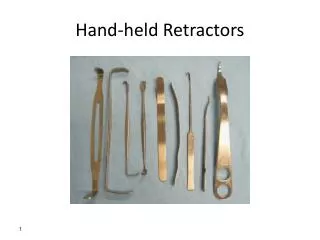
Antenna Concepts “Higher Is Better” Directionality Omnidirectional Directional Gain Measured in dB Larger number can mean greater range Antenna Cables Use minimum length required Polarization
Types of Antennas TermDefinition Dipole Radiates RF horizontally in all directions Omni-Directional See dipole Patch Radiates in a flashlight-like pattern Yagi Radiates in a focused flashlight-like pattern
Omni-Directional Antenna Patterns Side Above
Omni-Directional Gain Antenna Patterns Side Above
Step One Place Master AP at edge of required coverage area Perform site survey with Point to Point Site Survey Record minimum pkt/sec boundary Ensure coverage down sides of the inside wall
Surveying the Area I C I D D J H F B E G A Start by placing Access Point at Location A Perform site survey with Point to Point Site Survey, recording minimum pkt/sec boundary Move to Location C and repeat process
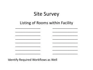
Documentation All documentation should be very clear and concise Leave no room for interpretation List all components needed for installation Provide RF coverage maps including PPS and signal strength observations Include special antenna & cable requirements Include Interference observations and explanations