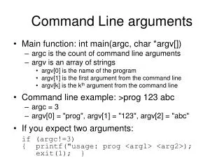
Draw lines using the LINE command and its options.
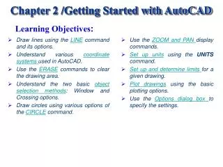
Learning Objectives :. Draw lines using the LINE command and its options. Understand various coordinate systems used in AutoCAD. Use the ERASE commands to clear the drawing area. Understand the two basic object selection methods : Window and Crossing options.

Draw lines using the LINE command and its options.
E N D
Presentation Transcript
Learning Objectives: • Draw lines using the LINE command and its options. • Understand various coordinate systems used in AutoCAD. • Use the ERASE commands to clear the drawing area. • Understand the two basic object selection methods: Window and Crossing options. • Draw circles using various options of the CIRCLE command. • Use the ZOOM and PAN display commands. • Set up units using the UNITS command. • Set up and determine limits for a given drawing. • Plot drawings using the basic plotting options. • Use the Options dialog box to specify the settings.
DRAWING LINES IN AutoCAD You can invoke the LINE command by choosing the Line button in the Draw toolbar, or by choosing Line from the Draw menu, or by entering LINE at the Command prompt. Once you have invoked the LINE command, the next prompt, Specify first point, requires you to specify the starting point of the line. You can either select a point using the pointing device After the first point is selected, AutoCAD will prompt you to enter the second point at the Specify next point or [Close/Undo]prompt. When you select the second point of the line, AutoCAD will again display the prompt Specify next point or [Close/Undo]. At this point you may continue to select points or terminate the LINEcommand by pressing Enter, ESC, or the Spacebar. Invoking the LINE command from the Draw toolbar Learning Objectives Invoking the LINE command from the Draw menu
The prompt sequence for the drawing, is as follows: Command:LINE« Specify first point: Move the cursor (mouse) and left-click to specify the first point. Specify next point or [Undo]: Move the cursor and left-click to specify the second point. Specify next point or [Undo]: Specify the third point. Specify next point or [Close/Undo]:«(Press ENTER to exit the LINE command.) Drawing lines using LINE command Learning Objectives
Command:LINE or L« (L is the command alias of the LINE command.) • Specify first point:Pick first point of the line. • Specify next point or [Undo]:Pick second point. • Specify next point or [Undo]:« • Command:LINE«(Or select Repeat Line from the shortcut menu.) • Specify first point:«(PressEnter or right-click to continue the line from the last line.) • Specify next point or [Undo]:Pick second point of second line (third point in the Figure). • Specify next point or [Undo]:« • The Continue Option To draw another line starting from the point where the previous line ended you can use the Continueoption. The following is the prompt sequence for the Continueoption: Using the Continue option with the Line command Learning Objectives
The Close Option The Closeoption can be used to join the current point with the initial point of the first line when two or more lines aredrawn in continuation. The following is the prompt sequence for the Close option for the figure: • Command: LINE« • Specify first point: Pick first point. • Specify next point or [Undo]:Pick second point. • Specify next point or [Undo]:Pick third point. • Specify next point or [Close/Undo]:Pick fourth point. • Specify next point or [Close/Undo]:C«(Joins the fourth point with the first point.) Using the Close option with the LINE command Learning Objectives
The Undo Option If you draw a line, and then realize that you made an error, you can remove the line using the Undo option. The following example illustrates the use of the Undooption for the figure: • Command:LINE or L« (L is command alias of LINE command) • Specify first point:Pickfirst point (Point 1 in the Figure). • Specify next point or [Undo]:Pick second point (Point 2). • Specify next point or [Undo]:Pick third point. • Specify next point or [Close/Undo]: Pick fourth point. • Specify next point or [Close/Undo]: U«(Removes last line from point 3 to point 4.) • Specify next point or [Close/Undo]: U«(Removes next line from point 2 to point 3. • Specify next point or [Close/Undo]:« Removing lines using the Undo option of the LINE command Learning Objectives
COORDINATE SYSTEMS To specify a point in a plane, we take two mutually perpendicular lines as references. The horizontal line is called the X axis, and the vertical line is called the Y axis. The point of intersection of these two axes is called the origin. The X coordinate measures the horizontal distance from the origin on the X axis. The Y coordinate measures the vertical distance from the origin on the Y axis. The origin has the coordinate values of X = 0, Y = 0. The origin is taken as the reference for locating any point in the XY plane. This method of specifying points is called the Cartesian coordinate system. Cartesian coordinate system Learning Objectives
TYPES OF COORDINATE SYSTEMS In AutoCAD, the default origin is located at the lower left corner of the graphics area of the screen. AutoCAD uses the following coordinate systems to locate a point in an XY plane: • Absolute Coordinate System • Relative Coordinate System • Direct Distance Entry Learning Objectives
Absolute Coordinate System In the absolute coordinate system the points are located with respect to the origin (0,0). For example, a point with X = 4 and Y = 3 is measured 4 units horizontally (displacement along the X axis) and 3 units vertically (displacement along the Y axis) from the origin. In AutoCAD, the absolute coordinates are specified by entering X and Y coordinates, separated by a comma. Absolute coordinate system Learning Objectives
Command: LINE« • Specify first point: 1,1« • (X = 1 and Y = 1.) • Specify next point or [Undo]: 4,1« • (X = 4 and Y = 1.) • Specify next point or [Undo]: 4,3« • Specify next point or [Close /Undo]: 1,3« • Specify next point or [Close/Undo]: 1,1« • Specify next point or [Close/Undo]:« Drawing lines using absolute coordinates Learning Objectives Coordinate Systems
Example 1 For figure, enter the absolute coordinates of the points in the following table. Then draw the figure using absolute coordinates. Save the drawing under the name Exam1.dwg. Point Coordinates Point Coordinates 1 3,1 5 5,2 2 3,6 6 6,3 3 4,6 7 7,3 4 4,2 8 7,1 To draw the figure the prompt sequence is: • Command:LINE« • Specify first point: 3,1«(Start point.) Drawing a figure using absolute coordinates Learning Objectives
Specify next point or [Undo]:3,6« • Specify next point or [Undo]: 4,6« • Specify next point or [Close/Undo]: 4,2« • Specify next point or [Close/Undo]: 5,2« • Specify next point or [close/Undo]: 6,3« • Specify next point or [close/Undo]: 7,3« • Specify next point or [close/Undo]: 7,1« • Specify next point or [close/Undo]: 3,1« • Specify next point or [close/Undo]:« Save this drawing. Enter SAVE at the Command prompt and then press ENTER. The Save Drawing As dialog box is displayed. Enter the name Exam2in the File name edit box to replace Drawing1.dwg and then choose the Save button. Learning Objectives Example 1
Exercise 1 For the figure, enter the absolute coordinates of the points, then use these coordinates to draw the same figure. The coordinates of Point 1 are 2, 1. Distance between the dotted lines is 1 unit. Drawing for Exercise 1 Learning Objectives
Relative Coordinate System There are two types of relative coordinates: • Relative Rectangular Coordinates • Relative Polar Coordinates Learning Objectives Coordinate Systems
Relative Rectangular Coordinates The following is the prompt sequence to draw a rectangle with the lower left corner at point (1,1). The length of the rectangle is 4 units and the width is 3 units. • Command: LINE« • Specify first point: 1,1«(Start point.) • Specify next point or [Undo]: @4,0«(Second point DX = 4, DY = 0.) • Specify next point or [Undo]:@0,3« (Third point DX = 0, DY = 3.) • Specify next point or [Close/Undo]: @-4,0« (Fourth point DX = -4, DY = 0.) • Specify next point or [close/Undo]: @0,-3«(Start point DX = 0, DY = -3.) • Specify next point or [close/Undo]:« Drawing lines using the relative rectangular coordinates Learning Objectives Relative Coordi System
Example 2 Draw the figure using relative rectangular coordinates of the points given in the table that follows. Point Coordinates Point Coordinates 1 3,1 8 @-1,-1 2 @4,0 9 @-1,1 3 @0,1 10 @-1,0 4 @-1,0 11 @0,-2 5 @1,1 12 @1,-1 6 @0,2 13 @-1,0 7 @-1,0 14 @0,-1 Using relative rectangular coordinates with the LINE command Learning Objectives
Once you know the coordinates of the points, you can draw the figure by using AutoCAD’sLINE command and entering the coordinates of the points. Specify next point or [Close/Undo]: @-1,1« Specify next point or [Close/Undo]: @-1,0« Specify next point or [Close/Undo]:@0,-2« Specify next point or [Close/Undo]: @1,-1« Specify next point or [Close/Undo]: @-1,0« Specify next point or [Close/Undo]: @0,-1« Specify next point or [Close/Undo]:« • Command: LINE« • Specify first point: 3,1« (Start point.) • Specify next point or [Undo]: @4,0« • Specify next point or [Undo]: @0,1« • Specify next point or [close/Undo]: @-1,0« • Specify next point or [Close/Undo]: @1,1« • Specify next point or [Close/Undo]: @0,2« • Specify next point or [Close/Undo]: @-1,0« • Specify next point or [Close/Undo]: @-1,-1« Learning Objectives Example 2
Exercise 2 For the figure, enter the relative rectangular coordinates of the points, then use these coordinates to draw the figure. The coordinates of Point 1 are 2, 1.The distance between the dotted lines is 1 unit. Drawing for Exercise 2 Learning Objectives
Relative Polar Coordinates In the relative polar coordinate system, a point can be located by defining both the distance of the point from the current point and the angle that the line between the two points makes with the positive X axis. The prompt sequence to draw a line from a point at 1,1 to a point at a distance of 5 units from the point (1,1), and at an angle of 30 degrees to the X axis is: • Command: LINE« • Specify first point: 1,1« • Specify next point or [Undo]: @5<30« Drawing a line using relative polar coordinates Learning Objectives Relative Coordi System
Example 3 For the figure, enter the relative polar coordinates of each point in the table, then generate the drawing. Use absolute coordinates for the start point (1.5, 1.75). The dimensions are shown in the drawing. Also, save this drawing as Exam3.dwg. Point Coordinates Point Coordinates 1 1.5,1.75 7 @1.0<180 2 @1.0<90 8 @0.5<270 3 @2.0<0 9 @1.0<0 4 @2.0<30 10 @1.25<270 5 @0.75<0 11 @0.75<180 6 @1.25<-90 12 @2.0<150 Drawing for Example 3 Learning Objectives
Once you know the coordinates of the points, you can generate the drawing by using AutoCAD’s LINEcommand and entering the coordinates of the points. Command:LINE« Specify first point: 1.5,1.75«(Start point.) Specify next point or [Undo]:@1<90« Specify next point or [Undo]: @2.0<0« Specify next point or [Close/Undo]:@2<30« Specify next point or [Close/Undo]:@0.75<0« Specify next point or [Close/Undo]:@1.25<-90« Specify next point or [Close/Undo]: @1.0<180« Specify next point or [Close/Undo]: @0.5<270« Specify next point or [Close/Undo]: @1.0<0« Specify next point or [Close/Undo]: @1.25<270« Specify next point or [Close/Undo]: @0.75<180« Specify next point or [Close/Undo]:@2.0<150« Specify next point or [Close/Undo]:C« (Joins the last point with the first point.) Save this drawing by entering SAVE at the Command prompt and then press ENTER. The Save Drawing As dialog box is displayed. Enter the name Exam3 in the File name edit box to replace Drawing1.dwg and then choose the Save button. The drawing will be saved with the given name in the My Documents directory. Learning Objectives Example 3
Exercise 3 • Draw the object as shown in the figure using the: • absolute • relative rectangular • relative polar coordinate • systems to locate the points. • Do not draw the dimensions; they are for reference only. Drawing for Exercise 3 Learning Objectives
Direct Distance Entry You can draw a line by specifying the length of the line and its direction, using the Direct Distance Entry. The direction is determined by the position of the cursor, and the length of the line is entered from the keyboard. If Ortho is on, you can draw lines along the X or Y axis by specifying the length of line and positioning the cursor along ortho direction. You can also use the direct distance entry with polar tracking and SNAPANG. Using the DirectDistanceEntry to draw lines • Command: LINE • Specify first point:Start point. • Specify next point or [Undo]: Position the cursor and then enter distance. • Specify next point or [Undo]: Position the cursor and then enter distance. Learning Objectives Coordinate Systems
Example 4 In this example you will draw the object as shown in the figure, using direct distance entry. The starting point is 2,2. In this example, you will use the polar tracking option to draw the lines. The default angle that is specified for polar tracking is 90-degree. As a result, you can use the polar tracking to draw lines at an angle that is divisible by 90. This is the reason, you first need to add another angle of 45-degree to the polar tracking that will allow you to track the lines drawn at an angle divisible by 45. Drawing for Example 4 Learning Objectives
The following is the Command prompt sequence for drawing the object in the figure : Command: LINE Specify first point: 2,2 Specify next point or [Close/Undo]: 2« (Move the cursor horizontally and enter the length of the line, 2, from the keyboard.) Specify next point or [Close/Undo]: .7071(Select POLAR in the status bar and position the cursor in a 45-degree direction and enter .7071.) Specify next point or [Close/Undo]: 1 Move the cursor up vertically, then enter 1. Specify next point or [Close/Undo]: 3 Move the cursor left horizontally, then enter 3. Specify next point or [Close/Undo]: 1 Move the cursor down vertically, then enter 1. Specify next point or [Close/Undo]: C Learning Objectives Example 4
Exercise 4 Use the direct distance entry method to draw a parallelogram. The base of the parallelogram equals 4 units, the side equals 2.25 units, and the angle equals 45 degrees. Draw the same parallelogram using absolute, relative, and polar coordinates. Note the differences and the advantage of using direct distance entry. Learning Objectives
ERASING OBJECTS After drawing some objects you may want to erase some of them from the screen. To erase you can use AutoCAD’s ERASEcommand. Invoking the ERASE command from the Modify toolbar The following is the prompt sequence for the figure shown: • Command: ERASE« • Select objects: Select first object. • Select objects: Select second object. • Select objects:« Selecting objects by positioning the pick box at the top of the object and then pressing the pick button on the pointing device Learning Objectives
CANCELING AND UNDOING A COMMAND If you are in a command and you want to cancel or get out of that command, press the Esc (Escape) key on the keyboard. • Command: ERASE« • Select objects: Press Esc (Escape) to cancel the command. The OOPS command restores objects that have been accidentally erased by the previous ERASE command. You can also use the U (Undo) command to undo the last command. • Command: OOPS« (Restores erased objects.) • Command: U« (Undoes the last command.) Use of the OOPS command Learning Objectives
OBJECT SELECTION METHODS One of the ways to select objects is to select them individually, which can be time consuming if you have a number of objects to edit. This problem can be solved by creating a selection set that enables you to select several objects at a time. The options available are: • The Window Option • The Crossing Option Learning Objectives
The Window Option This option is used to select an object or group of objects by enclosing them by a box or window. The objects to be selected should be completely enclosed within the window; those objects that lie partially inside the boundaries of the window are not selected. You can select the Windowoption by typing W at the Select objects: prompt. You can also select theWindowoption by selecting a blank point on the screen at theSelect objects: prompt. This is automatically taken as the first corner of the window. Dragging the cursor to the right will display a window. After selecting all the objects you can specify the other corner with your pointing device. Selecting objects using the Window option Learning Objectives Object Selection
The Crossing Option This option is used to select an object or group of objects by creating a box or window around them. The objects to be selected should be touching the window boundaries or completely enclosed within the window. You can select the Crossing option by typing C at the Select objects: prompt. You can also select theCrossing option by selecting a blank point on the screen at theSelect objects: prompt. This is automatically taken as the first corner of the window. Dragging the cursor to the left will display a window. After selecting all the objects you can specify the other corner with your pointing device. Selecting objects using the Crossing option Learning Objectives Object Selection
DRAWING CIRCLES To draw a circle you can use the AutoCAD CIRCLE command. The following is the prompt sequence for the CIRCLEcommand: Invoking the CIRCLE command from the Draw toolbar Command: CIRCLE« Specify center point for circle or [3P/2P/Ttr (tan tan radius)]: Invoking the CIRCLE command from the Draw menu Learning Objectives
The Center and Radius Option • The Center and Diameter Option • The Two-Point Option • The Three-Point Option • The Tangent Tangent Radius Option • The Tangent, Tangent, Tangent Option Learning Objectives
The Center and Radius Option In this option you can draw a circle by defining the center and the radius of the circle. In this option, AutoCAD lets you draw the circle by specifying the center point and the radius of the circle. For example, if you want to draw a circle with a center at 3,2 and a radius of 1 unit you can use the CIRCLE command in the following sequence: • Command: CIRCLE« • Specify center point for circle or [3P/2P/Ttr(tan tan radius):3,2« • Specify radius of circle or [Diameter]<current>:1« Drawing a circle using the CenterandRadius option Learning Objectives CIRCLE Options
The Center and Diameter Option In this option you can draw a circle by defining the center and diameter of the circle. In this option, AutoCAD lets you draw the circle by specifying the center point and the diameter of the circle. For example, if you want to draw a circle with a center at (2,3) and a diameter of 2 units you can use the CIRCLE command with the Diameter option in the following sequence: Command: CIRCLE« Specify center point for circle or [3P/2P/Ttr(tan tan radius): 2,3« Specify radius of circle or [Diameter]<current>:D« Specify diameter of circle <current>: 2« Drawing a circle using the CenterandDiameter option Learning Objectives CIRCLE Options
The Two-Point Option You can also draw a circle using the Two-Point option. In this option AutoCAD lets you draw the circle by specifying the two endpoints of the circle’s diameter. For example, if you want to draw a circle that passes through the points (1,1) and (2,1), you can use the CIRCLE command with 2P option, in the following sequence: Command: CIRCLE« Specify center point for circle or [3P/2P/Ttr(tan tan radius):2P« Specify first endpoint of circle’s diameter: 1,1« Second endpoint of circle’s diameter: 2,1«(You can also use the relative coordinates.) Drawing a circle using the Two-Point option Learning Objectives CIRCLE Options
The Three-Point Option For drawing a circle, you can also use the Three-Point option by defining three points on the circumference of the circle. The three points may be entered in any order. To draw a circle that passes through the points 3,3, 3,1 and 4,2, the prompt sequence is: Command: CIRCLE« Specify center point for circle or [3P/2P/Ttr(tan tan radius)]: 3P« Specify first point on circle: 3,3« Specify second point on circle: 3,1« Specify third point on circle:4,2« Drawing a circle using the Three-Point option Learning Objectives CIRCLE Options
The Tangent Tangent Radius Option A tangent is an object (line, circle, or arc) that contacts the circumference of a circle at only one point. In this option AutoCAD uses the Tangent object snap to locate two tangent points on the selected objects that are to be tangents to the circle. Then you have to specify the radius of the circle. The prompt sequence for drawing a circle using the Ttroption is: • Command: CIRCLE« • Specify center point for circle or [3P/2P/Ttr(tan tan radius)]: T« • Specify point on object for first tangent of circle: Select first line, circle, or arc. • Specify point on object for second tangent of circle: Select second line, circle, or arc. • Specify radius of circle <current>: 0.75« Learning Objectives
Drawing a circle using the tangent, tangent, radius(Ttr) option Tangent, tangent, radius(Ttr) option Learning Objectives
Tangent, tangent, radius option Tangent, tangent, radius (Ttr) option Learning Objectives CIRCLE Options
The Tangent, Tangent, Tangent Option This option is a modification of the Three-Point option. In this option AutoCAD uses the Tangent osnap to locate three points on three selected objects to which the circle is drawn tangent. The following is the prompt sequence for drawing a circle using the Tan, Tan, Tanoption: Command:CIRCLE« Specify center point for circle or [3P/2P/Ttr(tan tan radius): Select Tan, Tan, Tan option from the Draw menu. _ 3P Specify first point on circle: _tan to Select the first object. Specify second point on circle: _tan to Select the second object. Specify third point on circle: _tan to Select the third object. Drawing a circle using the Tan, Tan, Tan option Learning Objectives CIRCLE Options
Exercise 5 Draw the figure using different options of the LINE and CIRCLEcommands. Use absolute, relative rectangular, or relative polar coordinates for drawing the triangle. The vertices of the triangle will be used as the center of the circles. The circles can be drawn using the Center and Radius, Center and Diameter, or Tan, Tan, Tan option. (Height of triangle = 4.5 x sin 60 = 3.897.) Do not draw the dimensions; they are for reference only. Drawing for Exercise 5 Learning Objectives
BASIC DISPLAY COMMANDS Sometimes while drawing, it is very difficult to see and alter minute details. In AutoCAD, you can overcome this problem by viewing only a specific portion of the drawing. This is done using the ZOOM command. This command lets you enlarge or reduce the size of the drawing displayed on the screen. Some of the drawing display commands such as ZOOM and PAN will be introduced here. • Zooming the Drawings • Panning in Realtime Learning Objectives
Zooming the Drawings The ZOOMcommand enlarges or reduces the view of the drawing on the screen, but it does not affect the actual size of the entities. After the ZOOM command has been invoked, different options can be used to obtain the desired display. The following is the prompt sequence of the ZOOM command: Selecting Zoom options from the Standard toolbar Command: ZOOMorZ« Specify corner of window, enter a scale factor (nX or nXP), or [All/Center/Dynamic/Extents/Previous/Scale/Window]<real time>: Invoking the ZOOM command from the View menu Learning Objectives
The various options under ZOOM command are: • Realtime Zooming • Window Option • Previous Option • All Option Learning Objectives Basic Display Commands
Realtime Zooming You can use the Realtime Zoom to zoom in and zoom out interactively. To zoom in, invoke the command, then hold the pick button down and move the cursor up. Similarly, to zoom out, hold the pick button down and move the cursor down. Realtime zoom is the default setting for the ZOOM command. At the Command prompt, pressing ENTER after invoking the ZOOM command automatically invokes the realtime zoom. • Window Option This is the most commonly used option of the ZOOM command. It lets you specify the area you want to zoom in on by letting you specify two opposite corners of a rectangular window. Learning Objectives ZOOM Options
Previous Option While working on a complex drawing, you may need to zoom in on a portion of the drawing to edit some minute details. When you have completed the editing you may want to return to the previous view. • All Option This option zooms to the drawing limits or the extents, whichever is greater. Sometimes it is possible that the objects are drawn beyond the limits. In such a case the Zoom Alloption zooms to fill the drawn objects in the drawing area irrespective of its limits. Learning Objectives ZOOM Options
Panning in Realtime You can use the Realtime Pan to pan the drawing interactively, by sliding the drawing and placing it at the required position. When you select the realtime pan, AutoCAD displays an image of a hand indicating that you are in PAN mode. You can drag the hand anywhere on the screen to move the drawing. Learning Objectives Basic Display Commands
SETTING UNITS If you want to change the units while you are already working on a drawing, the UNITS command can be used. • Setting Units Using the Drawing Units Dialog Box The UNITS command is used to select a format for the units of distance and angle measurement. You can invoke this command using the Format menu, see figure. The UNITS command displays the DrawingUnits dialog box as shown in figure. You can then specify the precision for the units and angles from the corresponding Precision drop-down list, see figure. DrawingUnits dialog box Invoking the UNITS command from the Format menu Learning Objectives Specifying Precision from the DrawingUnits dialog box
Specifying Units In the Drawing Unitsdialog box, you can select a desired format of units from the drop-down list displayed when you choose the down arrow to the right of Type edit box. You can select one of the following five formats: 1. Architectural (0'-01/16") 2. Decimal (0.00) 3. Engineering (0'-0.00") 4. Fractional (0 1/16) 5. Scientific (0.00E+01) In the following example, the units are set as decimal, scientific, fractional, and decimal and fractional to enter the coordinates of different points: Command: LINE« Specify from point: 1.75,0.75«(Decimal.) Specify next point or [Undo]: 1.75E+01, 3.5E+00«(Scientific.) Specify next point or [Undo]: 10-3/8,8-3/4«(Fractional.) Specify next point or [Close/Undo]: 0.5,17/4«(Decimal and fractional.) Learning Objectives