L12
L12. Chapter 4 Circuit Theorems. From Chapter 2: Basic laws -- Foundations. From Chapter 3: Mesh analysis, Nodal analysis . Systematic tools, can be used for complex circuits. More useful tools to be learned in Chapter 4: Linearity Superposition

L12
E N D
Presentation Transcript
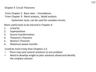
L12 Chapter 4 Circuit Theorems From Chapter 2: Basic laws-- Foundations. From Chapter 3: Mesh analysis, Nodal analysis. Systematic tools, can be used for complex circuits. More useful tools to be learned in Chapter 4: Linearity Superposition Source transformation Thevenin’s Theorem Norton’s Theorem Maximum power transfer • Could be more tricky than Chapters 2,3. • There may exist several solutions to one problem • Need to develop insight to plan solutions ahead and identify the simplest solution
L12 §4.2 Linearity i0 Basic concepts: Input, output 6 Input: the cause, or excitation, 4 4 Output: voltage or current of any element + - Is Vs 2 5 Example: 12 7 • Two inputs • Vs, Is • Two outputs: • i0, v0 You can imagine pulling out the inputs, outputs and put the rest inside a box vs Is + - i
L12 Pull out the inputs, outputs and put the rest inside a box More abstract form Input output First consider a circuit with one input, one output: Input output relationshipcan be described by a function i0 Resistive circuit Vs i0 Vs + - Circuit System Is 6 v0 Is Circuit System output Input
L12 Input output relationship: Input : can be , Output : can be of any element Circuit System output Input The input output relationship is said to be linear if for a certain constant . Linearity: Linearity = homogeneity + additivity Two implications: If x1 y1, Homogeneity: then ax1 a y1 Additivity: If x1 y1, then x1+ x2 y1+ y2 x2 y2,
L12 Linear circuit: the input-output relationship of a resistive circuit is linear. vo=k1Vs i0=k2Vs vo=k3Is i0=k4Is Linearity is the simplest relationship between input and output It is predictable: double efforts double results If Then We first use one example to demonstrate linearity Later on, we use this linear property to analyze circuits i0 Resistive circuit i0 Resistive circuit Is Vs + - + - + -
L12 Example: Input: Vs Output: I0 2 8 A resistive circuit. There exists a such that I0=Vs I0 4 ) i1 i2 6 + - Vs • What is ? • Use mesh analysis to find . + - 4 Solving (1) and (2): Assign mesh currents i1, i2. vx=2i1 I0 = i2= Vs 3vx= 6i1 I0= i2 Compare with I0=Vs 2i1+4(i1-i2)+Vs+6i1=0 KVL along mesh 1: 12i1-4i2= -Vs (1) 8i2- 3vx+4i2-Vs+4(i2-i1) = 0 KVL along mesh 2: 8i2- 6i1 +4i2-Vs+4(i2-i1) = 0 -10i1+16i2 = Vs (2)
L12 For this circuit, the input output relationship is derived by solving the output from the input Linear Circuit The direct approach Given input find output, output Input For some circuit, it is more convenient to find the inputfrom the output. Given output find input, The backward approach In general, for a certain How to find ? Just need one pair to determine If you know any pair of input output, Then Direct approach: Assume , find Backward approach: Assume , find
R7 A practice problem from Chapter 2: + - is the input, the cause is the output, the result Assume Practice 20: Find Vs for the circuit 6 I1=2A 4 10 9
L12 Example: Input: Output: Find such that Use backward method You may assume to be any number. Assume , With solved, you have 6 3 2 5 4 7
L12 Solution: Assign additional variables as in the following circuit: Is I2 v2, v3 arenode voltages I0 3 6 I1 I3 2 5 Is 4 7 Conclusion: The input-output relationship is I0=1A Starting with I0=1A By Ohm’s law: v0=5I0=5V; v1=3I0=3V By KVL: v2=v0+v1=5+3=8V By Ohms Law: I1=v2/4=2A By KCL at v2: I2=I0+I1=1+2=3A By (*): v3=v2+2I2=8+2*3=14V By Ohms Law: I3=v3/7=14/7=2A By KCL at v3: Is=I2+I3=3+2=5A I0=Is= 0.2Is If Is=15A, then I0=0.2*15=3A If Is=10A, then Is=5A I0=0.2*10=2A With I0=0.2Is, you can find output Io for any input Is You can also find the input for any output
L12 A simple demonstration: Suppose For 3 6 2 5 Is 4 7 What if is replaced by For 3 6 2 5 Vs 4 7
L12 §4.3 Superposition -- About the relationship between one output and several inputs Superposition principle: the voltage across (or current through) an element in a linear circuit, is the sum of voltage/current due to each independentsource alone. + - + - v0= v1+v2 i0= i1+ i2 Vs Due to Vs alone: turn off Set Is= 0 replace current source with open circuit i0 Is Due to Is alone: turn off Set Vs= 0 replace voltage source with short circuit + - Vs i1 i2 Is + - + -
L12 Key points: when you examine the effect due to one source, turn off the other sources • Turn off voltage source with short circuit • Turn of current source with open circuit
L12 Example : Find the output v. Step 1: Due to 6V – turn off 3A with open circuit 8Ω 3A 6V 4Ω + - + - v = v1+v2 = 2+8=10V By voltage division: Step 2: Due to 3A – turn off 6V with short circuit 8Ω By equivalent resistance and ohm’s law 6V 4Ω Superposition breaks down a circuit into several circuits with only one independent source – typically can be solved with simple methods in Chapter 2. 8Ω 3A 4Ω
Test 3 will be given on 4/8/13 (Monday), on Chapter 4 Quiz 5 will be given next Monday 3/25/13 on Linearity
R12 Practice 1: Find v0 for Vs=27V by linearity 4 2 4 2 Vs 3 3 + - Step 1: Find k such that v0=kVs by assuming v0= some value Step 2: For Vs=27V, v0= k Vs
R12 Practice 2: Find i using linearity 8Ω 4Ω i 4Ω 3A 3Ω
R12 Practice 3: Find i using superposition. 24V 8Ω + - + - 4Ω i 4Ω 3A 12V 3Ω
R12 Practice 4: Find i using superposition. 1Ω 6A 24V + - i 4Ω 3Ω 4Ω
Example: Find I0 using superposition. L13 Due to 7V: 6Ω 6Ω I0 I1 8Ω 4Ω 8Ω 4Ω + - + - 7V 3Ω 7V 3Ω 7A Due to 7A: 6Ω Due to 7V: replace 7A with open circuit Due to 7A: replace 7V with short circuit I2 8Ω 4Ω 3Ω 7A
L13 Due to 7A: 6Ω 6Ω I2 I2 8Ω 8Ω 4Ω 4Ω 3Ω 3Ω 7A 7A I2 8Ω 4Ω 7A 8Ω I2 6Ω 3Ω 4Ω 3Ω 6Ω 7A I2 10Ω 4Ω 7A
L13 Due to 7V: 6Ω with respect to / I1 8Ω 4Ω + - 7V By current division: 3Ω Going back to the original circuit:
L13 Superposition with dependent sources: For circuit with dependent sources, keep the dependent sources. They cannot be turned off . They are not input Example: Find vab using superposition: + - + - + - + - + - By KVL: , 10Ω 3vab 4V 2A 10Ω 3v2 10Ω 3v1 Due to 2A Due to 4V 2A 4V
L13 § 4.4: Source transformation A general situation: you can separate a circuit as the connection of two parts. i Circuit A Circuit C For circuit A, you can obtain a function v = f (i) If there is another circuit B, with the same vi relationship, You can replace Circuit A with Circuit B without affecting Circuit C All variables in Circuit C are unchanged, But the variables in Circuit A may not exist in Circuit B. i Sometimes you need to replace a complex circuit witha simpler one; as with Thevenin’s equivalent Sometimes with one which is more convenient for analysisas with source transformation Circuit B Circuit C
L13 Compare the two connections: Circuit B: Circuit A: i i What is the vi relationship for each circuit? How to express v in terms of i? iR R1 is + - R2 vs By KCL, iR= is-I v = R2iR= R2is- R2i By KVL, v = vs-vR= vs-R1i v = R2is- R2i v = vs-R1i To have the same vi relationship: R1=R2, Vs=R2is
L13 Conclusion: The following two connections are equivalent + - If you replace one with another, the rest of the circuitwill not be affected. However, be careful: The voltages across resistor R in the two circuits are different; The currents through R in the two circuits also different. i i iR R vs= Ris is R vs
L13 Extension to dependent sources: The following two connections are equivalent i i R vs= Ris is R vs + - For example, if is= kvx, then vs=Ris=Rkvx If vs= ki0, then is=ki0/R The rule: if you put the two sources side by side, the arrow of the current source points from – to + of the voltage source
L13 All equivalent i i R vs= Ris is + - R vs i i + - is vs R R
L13 Example: Find the voltage v0 using source transformation a 2Ω 3Ω 4Ω Caution: Need to keep the two nodes “a” and “b”so that v0 is kept after every change 8Ω 12V 3A b + - + - After these transformations, 4Ω and 2Ω can be combined, 3Ω and 8Ωcan be combined. Reducing the numberof elements a 2Ω 4Ω 4A 8Ω 3Ω b 12V When everythingin parallel, you can rearrange the elementswithout changing the voltage and branch current. a 4A 2A 6Ω 3Ω 8Ω b
L13 When everythingin parallel, you can rearrange the elementswithout changing the voltage and branch current. v0=3.2V 2A b a 4A 2A 6Ω 3Ω 8Ω b a a 2A 4A 3Ω 1.6Ω 8Ω 6Ω b
L13 Example: Find vx 4Ω 0.25vx Combine parallel resistors 6V 2Ω 2Ω 18V 4Ω//2Ω//2Ω=0.8Ω + - + - + - Combine parallelcurrent sources + - 4Ω vx 3A 2Ω 18V 2Ω vx=7.5V 3A 4Ω 2Ω 2Ω 0.8Ω
R13 Practice 5: Find v0 using source transformation 6Ω 5Ω + - 3Ω 9V 9v0 + - 2Ω
R13 Practice 6: Find v0 using source transformation + - 3A 2Ω 3Ω 4A 2Ω 2A 10V 2Ω
R13 Practice 7: Find I0 using source transformation 4Ω I0 1Ω v0/3 + - 8V 6Ω


![L12- FLUIDS [1]](https://cdn0.slideserve.com/1254585/l12-fluids-1-dt.jpg)

![L12- FLUIDS [1]](https://cdn5.slideserve.com/9298332/l12-fluids-1-dt.jpg)