Ground Clutter Background
Ground Clutter Background. NCAR receives outside funding from NOAA to improve the operational radar network (WSR-88D) data quality Over 160 radars and 3 agencies (NOAA, FAA, DOD) Currently Single Pol Dual-Pol update planned Can use S-Pol for development Single Pol Dual-Pol.

Ground Clutter Background
E N D
Presentation Transcript
Ground Clutter Background • NCAR receives outside funding from NOAA to improve the operational radar network (WSR-88D) data quality • Over 160 radars and 3 agencies (NOAA, FAA, DOD) • Currently Single Pol • Dual-Pol update planned • Can use S-Pol for development • Single Pol • Dual-Pol
SUPER REFRACTION AP NORMAL REFRACTION NP SUB REFRACTION AP DUCTING AP Background: Clutter Types • Two types of ground clutter • Normally propagated (NP) • Obstacles in direct path of radar beam (towers, mountains…) • Always in same location • Anomalously propagated (AP) • Atmospheric conditions refract beam (or side lobes) into ground (super-refraction) • Ducting causes widespread AP clutter • Can evolve rapidly
Background: Refraction Regimes • Beam propagation depends on vertical gradient of refractivity N • N = (n-1) x 106, where n is the refractive index dN/dz > 0 Subrefraction 0 > dN/dz > -0.0787 Normal refraction -0.0787 > dN/dz > -0.157 Super-refraction -0.157 > dN/dz Ducting
Background: AP Causes • T inversion from nocturnal radiative cooling • T inversion over moist PBL through subsidence in tradewind region • Dry air advection over sea surface • Low level moist/cool air advection • Thunderstorm outflow
Background • Global frequency of super refraction and ducting (Courtesy Philippe Lopez, ECMWF)
Background • Global frequency of super refraction and ducting (Courtesy Philippe Lopez, ECMWF)
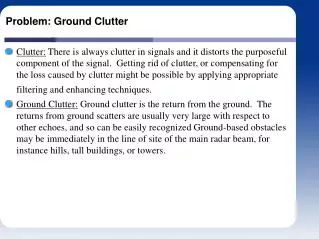
Background: Impacts • Ground clutter echoes bias the moment estimates in weather • Reflectivity biased high • Radar-estimated rain rates • False aviation hazards etc… • Radial velocity biased towards 0 m/s • Velocity spectrum width biased towards 0 m/s
Reflectivity (dBZ) Radial velocity (m/s) Radar-estimated rain accumulation (mm)
Background: Impacts • Filters can effectively remove clutter contamination • May not remove all clutter in some cases – clutter residue • Two types • Time domain (IIR and FIR elliptic high pass filters) • Results in suppression of power near 0 m/s velocity • WSR-88D legacy 5 Pol IIR filter • Spectral domain • New WSR-88D processor • S-Pol Hawk processor
Time domain and spectral domain review Transmitter pulses as the antenna scans (~ 1 ms-1)
Power Phase Time Time Taking Fourier transform of time series sorts the power into the appropriate frequency, or radial velocity Power Velocity Time domain and spectral domain review The processor groups N pulses to compute moments at a range gate The I and Q values of these pulses constitutes the time series data
WSR-88D Clutter Filter Suppression Level Low Medium High Vs (m/s) 0.7095 0.9375 1.3875 Vp (m/s) 1.1825 1.5625 2.3125 Power -Vp -Vs 0 Vs Vp Velocity Various time domain clutter filter suppression levels S-Pol Viraq: Vp = 0.5 m/s
WSR-88D clutter filter response From Sirmans, 1992
The Problem • Time series ground clutter cancellers largely eliminate ground returns • However, clutter cancellers also bias the moment estimates in weather (near 0 m/s radial velocity) • Z biased low (1 to 15 dB) • Radar-estimated rain rates (7 dB bias = 2/3 loss in rain rate) • V biased away 0 m/s
Clutter filter notch Memphis NEXRAD time series data 10log10(I2 + Q2) -15 -10 -5 0 5 10 15 Velocity (m/s)
The Problem • Time series ground clutter cancellers largely eliminate ground returns • However, clutter cancellers also bias the moment estimates in weather (near 0 m/s radial velocity) • Z biased low (1 to 15 dB) • Radar-estimated rain rates (7 dB bias = 2/3 loss in rain rate) • V biased away 0 m/s • Let’s look at some examples in the spectral domain
Clutter filter notch KNQA time series data
Velocity (m/s) -10 –6 –2 0 2 6 10 Clutter Filter biases • Generate family of Gaussian approximations to weather spectra for expected V and W values V = 1.0 m s-1 W = 2 m s-1
Vfilt =1.73 ms-1 Wfilt =2.54 ms-1 Pfilt = 1.73 -10 –6 –2 0 2 6 10 Velocity (m/s) Clutter Filter biases V = 1.0 m s-1 W= 2 m s-1 Punfilt = 2.54 -10 –6 –2 0 2 6 10 Velocity (m/s)
Data Simulated Comparison of simulated values and data 4 2 Vunfilt – Vfilt (m/s) 0 -2 -4 -15 -10 -5 0 5 10 Vunfilt (m/s)
Simulated Data Comparison of table values and data 2 0 Wunfilt – Wfilt (m/s) -2 -4 -15 -10 -5 0 5 10 Vunfilt (m/s)
Background: Spectral Filters • Modern ground clutter filters operate in the spectral domain • Eliminate ground returns • Compensate weather echoes for clutter filter loss • Compensation does not work well for narrow spectrum width weather • Therefore, clutter filters bias the moment estimates in weather echoes (near 0 m/s radial velocity) • Z biased low (1 to 15 dB) • Radar-estimated rain rates (7 dB bias = 2/3 loss in rain rate) • V biased away 0 m/s
Ground clutter Ground clutter Clutter and weather #1 Weather Weather Filter -Vn 0 Vn -Vn 0 Vn Filter Background – some spectral cartoons Clutter only Ground clutter Ground clutter -Vn 0 Vn -Vn 0 Vn
Gaussian interpolation Gaussian interpolation Background – some spectral cartoons Wide weather only Weather Filter -Vn 0 Vn -Vn 0 Vn Narrow weather only Weather Filter -Vn 0 Vn -Vn 0 Vn
Ground clutter Ground clutter Weather Weather Filter -Vn 0 Vn -Vn 0 Vn Background – some spectral cartoons Clutter and weather #2
Background Example of clutter filter bias in weather Zero isodop Zero isodop Reflectivity (dBZ) Radial Velocity (kt)
Ground Clutter Mitigation • Solution is to automatically identify gates with clutter contamination • Apply spectral clutter filter only to gates identified • Real time – Radar output is free of clutter contamination • Clutter Mitigation Decision (CMD) runs on S-Pol • Fuzzy logic • Real time
What is fuzzy logic? Principle: Superset of conventional logic, extended to use partial truth between completely true [1] and completely false [0] Founder: Lotfi A. Zadeh, Berkeley, 1960 Fuzzy logic is used directly in e.g. : Linear and Nonlinear Control Pattern Recognition Financial Systems Operation Research Data Analysis Alternative: neural networks – needs sufficient truth data sets to learn
How does fuzzy logic work? Pre-fuzzy step: Determine inputs with skill for the given problem – Feature Fields Step 1 - Fuzzification: Membership function for each feature field indicates degree of membership: 0 for non membership 1 for full membership and transition 0< v <1 described with e.g. triangle, gaussian, trapezoid ….. Membership function applied to feature fields obtaining the “interest values” Step 2 – Inference: Truth value for premise of given individual rules (Min. or Product) are applied Step 3 – Composition: All fuzzy subsets assigned to each output variable are combined to form a single fuzzy subset (Max. or Sum) Step 4 – Defuzzification: Convert fuzzy output to a crisp number From:http://www.mathworks.com/cmsimages/fl_mainimage_wl_3248.gif
Fuzzy Logic CMD Algorithm • Identify parameters that distinguish weather and clutter data (called feature fields) • Reflectivity in clutter has higher variance than weather • Compute texture • Computed along a single beam (9 gates) • Squared change in dBZ from one gate to the next averaged over kernal • Compute SPIN change – computed along a single beam (11 gates) • Count of reflectivity trend changes Count the number of significant gradient sign reversals
Fuzzy Logic CMD Algorithm • Identify parameters that distinguish weather and clutter data (called feature fields) • Differential reflectivity (ZDR) in clutter has higher variance than weather • Compute standard deviation of ZDR • Computed along a single beam (5 gates) • Differential phase (PHIDP) in clutter has higher variance than weather • Compute standard deviation of PHIDP • Computed along a single beam (5 gates) • Clutter has constant phase • Compute clutter phase alignment (CPA) from time series – computed at single range gates
Clutter Phase Alignment - CPA hhi CPA = Time series of I&Q • In clutter, the phase of each pulse in the time series for a particular gate is almost constant since the clutter does not move much and is at a constant distance from the radar. • In noise, the phase from pulse to pulse is random. • In weather, the phase from pulse to pulse will vary depending on the velocity of the targets within the illumination volume. hhi
CPA Phasor Diagrams Adding the complex I&Q samples at a gate Noise or weather with non-zero velocity Clutter Weather mixed with clutter
Normalized Histograms in Clutter Mixed with weather at various CSR values Membership Function
Normalized Histograms in Clutter Mixed with weather at various CSR values Membership Function
Design Membership functions (2.2, 1.0) (1.0, 0.0) (10.0, 1.0) (5.0, 0.0)
Fuzzy Logic CMD Algorithm Apply fuzzy rule Compute interest value (I) Compute Feature fields Compute weighted sum Input CPA SPIN Texture SD(ZDR) SD(FDP) High SPIN –OR- High TDBZ S(w*I) S(w) I and Q Apply threshold (0.5)