Download
1 / 10
100 likes | 190 Vues
Explore the perturbations and compensation schemes in injection painting for beam optics, highlighting motivation, simulation results, and conclusions. Learn about challenges and strategies for maximizing beam brightness.

E N D
Beam Optics and Painting SchemesC. Bracco, C. Carli, B. Goddard, J.-B. Lallement, M.Martini, W. Weterings Motivation for a H- Charge Exchange Injection Lattice Perturbations and their Compensation Injection Painting Apertures Typical Simulation Results Conclusions, Outlook, Questions
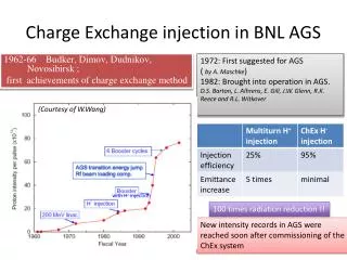
Motivation for a H- Charge Exchange Injection Reference trajectory without bumps Bending magnet BS3 BS4 BS1 BS2 Closed orbit with chicane and maximum painting bump Incoming H- Stripping foil Injection straight at the beginning of the injection (trajectory of incoming H- coincides with closed orbit) • Injected and circulating beam merged with a dipole BS2 • No septum separating space into region for injected beam and beam circulating in the PSB • No losses on the injection septum (~50% now for LHC beams) • Injection painting bump can decrease slowly allowing injecting a larger number of turns • High brightness beams possible in the Booster with a beam current lower than the one from Linac2 • New injection hardware required perturbing the lattice • Emittance increase due to Scattering of protons traversing the injection foil
Lattice Perturbations and their Compensation • Source of the problem: • Injection chicane and other hardware to be implemented within available straight section (with “fixed” geometry of incoming beam) • Short “strong” (for dipoles generating an orbit bump) BS magnets to create the chicane • Additional focusing created by BS magnets perturbs lattice • With rectangular magnets focusing in the vertical plane • With vertical tune close to half integer QV ~ 4.5 (even above half-integer resonance for highest brightness and intensity) strong beta-beating in the vertical plane • As long BS magnets as possible to reduce the additional focusing and compensation schemes (next slides)
Lattice Perturbations and their Compensation QDE03 and QDE14 appropriate for Compensating 2QV = 9 Injection straight section • “Active” compensation • Look for appropriate locations to add (time-varying) quadrupolar fields • Trims on QDE magnets (on additional windings …) in period 03 and 14 with appropriate phases • Effective compensation with large vertical b-functions (small horizontal perturbation small hor. b‘s) • Slow chicane fall (say 5 ms) to make sure that quad trim PCs can follow programmed currents • “Passive” compensation • Do not use R-Bends, but add pole-face rotations to bring part of perturbation in (less sensitive) horizontal plane • No perfect compensation during chicane fall, more difficult for magnets and power converters • Fast chicane fall possible and necessary without compensation currents (if Eddy currents are nor a problem)
Injection Painting • Longitudinal painting with energy modulation(just a brief recapitulation) • Transverse (horizontal) painting • Most simulations up to now assumed linear decrease of the painting bump • Transverse distribution with dense core and tails • Study started (by Chiara, see presentation by Luc Sermeus on KSWs in this BCC) on optimized painting bump with • fast decrease at the beginning to reduce density at the center • Slow decrease at the end of the injection to reduce tails • Fast decrease to move the beam away from the foil • Vertical emittances (beam sizes) with vert. offset and betatron mismatch (of injected beam)
Apertures (with zero dispersion of the incoming beam) Incoming beam: 10 mm offset, zero dispersion; circulating beam centered (“BeamScope” window with reduced aperture centered in say 4L1) and 35 mm painting bump, (compare with B.Goddards L4BCC presentation on 8th September 2009) “BeamScope” window reduces acceptance (in 2L1 for sketch) Conductor of septum-like BS2 magnet Black: maximum beam extension after painting bump decreased Red: positive energy offset part’s Blue: negative energy offset part’s Solid lines: beginning of injection Dashed: end of injection Injected beam
Apertures (with matched dispersion ofthe incoming beam) Incoming beam: 5 mm offset, zero dispersion; circulating beam off-centered (“BeamScope” window in 2L1 with reduced aperture and shifted by 10mm towards the inside) and 50 mm painting bump, Black: maximum beam extension after painting bump decreased Red: positive energy offset part’s Blue: negative energy offset part’s Solid lines: beginning of injection Dashed: end of injection
Typical simulation results(phase space plots with active compensation taken from M. Martini) turn 250 turn 19 turn 500 turn 1 turn 1000 turn 750 turn 1000 turn 250 turn 500 166 mp turn 1000 turn 750 turn 1000 turn 20 turn 3000 turn 5000 turn 1 turn 4000 turn 5000 turn 1000 turn 3000 turn 4000
Typical simulation results(emittance evolutions taken from M. Martini) Evolution of the horizontal (left image) and vertical (right image) emittances during about 10ms from the start of the injection • Fast emittance blow-up during injection and decrease of the injection chicane (500 turns for passive compensation and 5000 turns for active compensation) • Probably feasible to estimate beam properties with available programs • Slow blow-up afterwards • Difficult (impossible?) to estimate, depends on simulation parameter like number of macro-particles • Are machine imperfections (not taken into account at present) relevant?
Summary, Outlook, open Questions …… activities to be discussed and redefined with the new LIU structure • Compensation of lattice perturbations • Simulations indicate that both active and passive compensation give acceptable results (tendency: less losses with active compensation) • Additional power converters required for active compensation feasible • Very likely that active compensation will be the choice … simpler for BS magnets (and their power converters) • Aperture restriction (“BeamScope” like window) • Proposal to reduce the acceptance of the machine to have the foil out side the acceptance after the painting bum decrease … and possibly to install a rough collimation system • Are there still plans to study/install such a restriction … and activation in general? • Transverse painting optimization to be continued to to define matching parameters at the injection point (by Chiara …) • Effect on beam dynamics with direct space charge?! • Follow-up of longitudinal painting • PSB injection timings, definition of an application … • How to deal with longer energy modulation periods? • Investigations started … impact on scattering in foil? • Injection steering … not to forget: • Install and construct BI.DVT/DHZ50 & 70 • Required strengths estimated