Studies with the ATLAS Trigger & Data Acquisition "pre-series" setup
180 likes | 302 Vues
This document provides a comprehensive analysis of the ATLAS Trigger and Data Acquisition (TDAQ) pre-series setup conducted by N. Gökhan Ünel from UCI and CERN on behalf of the ATLAS TDAQ community. It details the first- and second-level trigger systems, data storage solutions, event handling, and subsystem performance related to the ATLAS detector at CERN's computer center. Key topics include network management, event filtering, and the optimization of readout and storage capabilities necessary for efficient data handling at the expected event rates.

Studies with the ATLAS Trigger & Data Acquisition "pre-series" setup
E N D
Presentation Transcript
Studies with the ATLAS Trigger & Data Acquisition "pre-series" setup • N. Gökhan Ünel (UCI & CERN) • on behalf of • ATLAS TDAQ community
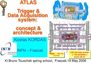
First- level trigger LVL2 Super- visor Network switches pROS pROS Data storage SDX1 Second- level trigger Local Storage SubFarm Outputs (SFOs) Read- Out Drivers (RODs) Event Builder SubFarm Inputs (SFIs) RoI Builder Network switches DataFlow Manager dual-CPU nodes Event Filter (EF) Read-Out Subsystems (ROSs) LVL2 farm ATLAS detector CERN computer centre ~30 ~1600 ~100 ~ 500 Event rate ~ 200 Hz stores LVL2 output stores LVL2 output Event data requests Delete commands Gigabit Ethernet Requested event data Event data pulled: partial events @ ≤ 100 kHz, full events @ ~ 3 kHz Regions Of Interest USA15 Data of events accepted by first-level trigger 1600 Read- Out Links ~150 PCs VME Dedicated links UX15 Timing Trigger Control (TTC) Event data pushed @ ≤ 100 kHz, 1600 fragments of ~ 1 kByte each ATLAS Trigger / DAQ Data Flow TDAQ Details: B. Grorini’s talk SDX1 USA15 UX15
5.5 Pre-series of final system8 racks at Point-1 (10% of final dataflow) Farm management details: M. Dobson’s talk One Full L2 rack-TDAQ rack- 30 HLT PCs Partial EF rack-TDAQ rack- 12 HLT PCs Partial ONLINE rack-TDAQ rack- 4 HLT PC(monitoring) 2 LE PC(control) 2 Central FileServers Partial Superv’r rack-TDAQ rack- 3 HE PCs RoIB rack-TC rack + horiz. cooling- 50% of RoIB Partial EFIO rack-TDAQ rack- 10 HE PC(6 SFI - 2 SFO - 2 DFM) One ROS rack-TC rack+ horiz. Cooling- 12 ROS 48 ROBINs One Switch rack-TDAQ rack- 128-port GEth for L2+EB surface: SDX1 underground : USA15 • ROS, L2, EFIO and EF racks:one Local File Server, one or more Local Switches • Machine Park: Dual Opteron and Xeon nodes, ROS nodes uniprocessor • OS issues: Net booted and diskless nodes (localdisks as scratch), runing Scientific Linux, Cern version3. • Trigger : Free trigger from L2SV or frequency manually set using LTP
ROS & ROBIN basics 3 input channels Custom design ROBIN card • a ROBIN card with 3 s-link fiber inputs is the basic readout system (ROS) unit. A typical ROS will house 4 such cards (4x3 =12 input channels). • ATLAS has ~1500 fiber links, ~150 ROS nodes. • ROS sw ensures the parallel processing of 12 input channels PCI readout ROS internal parameters adjusted to achieve maximum LVL1 rate
“Hottest” ROS from paper model “Hottest” ROS from paper model ROS studies Final ROS HW used UDP as n/w protocol ROS with 12 ROLs ROL size=1kB 1. A paper model is used to estimate ROS requirements 2. max LVL1 rate measured on final hardware 3. Zoom in to “ATLAS region” Performance of final ROS (PC+ROBIN) is already above requirements. ROD-ROS mapping optimization would further reduce ROS requirements. Low Lumi. operating region
Gigabit limit Linear behavior • EB subsystem parameters optimized using measurements on hardware. • Discrete event simulation modeling faithfully reproduces hardware measurements. We estimate final ATLAS would need ~80SFIs when 70% of the input bandwidth is utilized. EB studies • EB performance is understood in terms of Gigabit line speed and SFI performance. (No SFI output) • The used to predict the number of SFIs needed in final ATLAS
L2 & ROIB studies to calculate the time budged left for algorithms • We estimate 4-5 L2SVs can handle the load of full ATLAS.
Combined system -1 • The triggers are generated by the L2PUs driving the system as fast as possible. Stable operation observed even for overdriven cases. • L2PUs run without algorithms, with more parallel threads • each L2PU represents an LVL2 subfarm • Measurements and their simulations are in good agreement allowing to scale the simulations from preseries setup (~10%) to final ATLAS size. ATLAS nominal runs at 3.5% LVL2 accept ratio To be updated
Combined system -2 • Performance analysis here
Simulations • Scaling to full size, from simulations from Kris..
Adding Event Filter Event Filter details: K. Kordas’ talk • Output from SFI to EF nodes decreases maximum SFI throughput. • The throughput with EF saturates to about 80% of the maximum for large events. (typical ATLAS event ~1MB) • 80 / 0.80 = 100 SFIs needed for final ATLAS • 2EF nodes (w/o) algorithms are enough to saturate 1 SFI • 6 x2=12 EF nodes needed to drive the pre-series.
Adding SFO • Number of SFOs determined by disk I/O capacity & the requirement for disk space for ~24 hour independent running. • TDR assumed 15MB/s of throughput capacity on single disk: 30 PCs result therefore in 450 MB/s (200Hz x ~2MB) • Faster disk I/O and larger disks could mean less SFOs • RAID can bring protection against failures: • which raid level? Raid1, Raid5, Raid50 which filesystem ? hw1: cheap hw2: expensive 0.5 .. 1.5MB events
ROD start EB Data Path Trigger Path ROD ROIB L2PU L2SV Adding a detector • Using pre-series with Tile Calorimeter Barrel setup at the pit (16 ROLs in 8 ROBINs, 2 ROSs) • Possible Setups • Simple EB (DFM self trigger) • Combined (ROIB trigger) • Goals for this exercise: • Exercise the TDAQ chain (done) • Write data @ SFO level (done) • Use HLT sw to match μ tracks • (prevented by lack of time) ROS ROS DFM To Disc SFO EF SFI
Adding Monitoring SFI only • Alina’s work efficiency is obtained by comparing rates with and without monitoring SFI & ROS The goal is to determine max allowed monitoring frequency
Stability & Recovery issues • Force systematic failures in hardware and in software, check the system recovery • Almost all infrastructure application failures can be recovered • Apart from ROS, all DataFlow applications can be recovered. (ROS needs hardware handshake with detector side) • For hardware failures, Process Manager will be part of Unix services to reintegrate a dead node into TDAQ chain. Combined system stable run at 10% accept ratio for ~8.5 hours Fault tolerance and Recovery tests
Configuration Retrieval • Measure time it takes to dump data from large databases • can be done in a day • Can we scale up to final system?
Replaying physics data Algorithm details: K. Kordas’ talk • Event data files from simulation studies for different physics objects (muons, e, jet) were preloaded into ROS & ROIB • The whole TDAQ chain was triggered by the ROIB • Various physics algorithms were run at the LVL2 farm nodes to select events matching the required triggers • Selected events were assembled from all ROS and send to event filter farm For the first time we have realistic measurements on various algorithm execution times.
Next steps • Exploitation with algorithms • Garbage collection • State transition timing measurements • Preseries as a release testing environment Conclusions • Pre-series system has shown that ATLAS TDAQ operates reliably and up to the requirements. • We will be ready in time to match the LHC challenge.