Integrated Digital Services Network (ISDN)
Integrated Services Digital Network (ISDN) is a set of communication standards designed for the simultaneous transmission of voice, video, and data over traditional telephone networks. First defined in 1988, ISDN integrates speech and data on the same lines, providing features absent in analog systems. It supports different access interfaces like Basic Rate Interface (BRI) and Primary Rate Interface (PRI) and allows for improved voice quality and data transmission. ISDN is crucial for services such as internet access and videoconferencing, demonstrating its versatility in digital communications.

Integrated Digital Services Network (ISDN)
E N D
Presentation Transcript
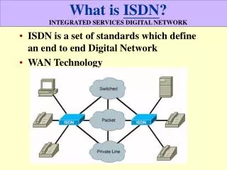
Introduction to ISDN • Integrated Services Digital Network (ISDN) is a set of communications standards for simultaneous digital transmission of voice, video, data, and other network services over the traditional circuits of the public switched telephone network. It was first defined in 1988 in the CCITT red book. Prior to ISDN, the phone system was viewed as a way to transport voice, with some special services available for data.The key feature of ISDN is that it integrates speech and data on the same lines, adding features that were not available in the classic telephone system. There are several kinds of access interfaces to ISDN defined as Basic Rate Interface (BRI), Primary Rate Interface (PRI) and Broadband ISDN (B-ISDN). • ISDN is a circuit-switched telephone network system, which also provides access to packet switched networks, designed to allow digital transmission of voice and data over ordinary telephone copper wires, resulting in potentially better voice quality than an analog phone can provide. It offers circuit-switched connections (for either voice or data), and packet-switched connections (for data), in increments of 64 kilobit/s. A major market application for ISDN in some countries is Internet access, where ISDN typically provides a maximum of 128 kbit/s in both upstream and downstream directions. Channel bonding can achieve a greater data rate; typically the ISDN B-channels of 3 or 4 BRIs (6 to 8 64 kbit/s channels) are bonded.
Introduction to ISDN Cont. • ISDN should not be mistaken for its use with a specific protocol, such as Q.931 whereby ISDN is employed as the network, data-link and physical layers in the context of the OSI model. In a broad sense ISDN can be considered a suite of digital services existing on layers 1, 2, and 3 of the OSI model. ISDN is designed to provide access to voice and data services simultaneously. • However, common use has reduced ISDN to be limited to Q.931 and related protocols, which are a set of protocols for establishing and breaking circuit switched connections, and for advanced call features for the user. They were introduced in 1986. • In a videoconference, ISDN provides simultaneous voice, video, and text transmission between individual desktop videoconferencing systems and group (room) videoconferencing systems.
ISDN Info • Circuit switched digital line • ISDN is typically used for dialup connectivity • ISDN define includes • Hardware • Call setup schemes • Channel allocation • ISDN provides two main channel types • Bearer channel (B channel) for data • Delta channel (D channel) for signaling
ISDN Bearer Channels • Each B channel provides 64 kbps full duplex bandwidth. • An ISDN connection with two B channels would provide a total usable bandwidth of 128 kbps. • Each B channel can be used independently • For example one can be used for digitized voice • And one for data
ISDN Delta Channel • ISDN uses the delta (D channel) for call setup and signaling. • The D channel carries signaling messages, such as call setup and teardown, to control calls on B channels. • This is called out-of-band signaling • The local switch uses the SS7 signaling protocol to set up a path and pass the called number to the remote ISDN switch. • As opposed to in-band signaling such as a normal phone line that uses the same line/channel for call setup as data • ISDN also delivers the numbers to the switch at D-channel rates, thus reducing the time it takes to set up the call • The D channel bandwidth is • 16 kbps for the Basic Rate Interface (BRI) • 64 kbps for the Primary Rate Interface (PRI)
ISDN Bundles • ISDN specifies two standard access methods, BRI and PRI. • A single BRI or PRI interface provides a multiplexed bundle of B and D channels.
Basic Rate Interface (BRI) • BRI • two 64 kbps B channels plus one 16kbps D channel. • also referred to as 2B+D. • BRI service is provided over a local copper loop that traditionally carries analog phone service. • While there is only one physical path for a BRI, there are three separate information paths, 2B+D. • Information from the three channels is multiplexed into the one physical path.
Primary Rate Interface (PRI) • North America and Japan • PRI offers 23 B channels and one D channel. • The same service as a T1 connection. • In Europe and much of the rest of the world • PRI offers 30 B channels and one D channel • The same service as a T1 connection • Remember that D channel for PRI is 64Kbps
ISDN 3 Layer Model • ISDN standards spanning the physical, data link, and network layers of the OSI reference model
ISDN Switch Type • Routers must be configured to identify the type of switch at the telco exchange (CO) with which they will communicate. • Different switch types have different D channel signaling protocols • ISDN switch types can vary even within Telstra • Available ISDN switch types vary, depending in part on the country in
Service Profile Identifiers (SPID) • A SPID is a number provided by the ISDN carrier to identify the line configuration of the BRI service. • SPIDs are a series of characters that usually resemble telephone numbers. • Each SPID points to line setup and configuration information. • SPIDs identify each B channel to the switch at the central office. • SPIDs allow multiple ISDN devices, such as voice and data equipment, to share the local loop.
ISDN Components • ISDN components include terminals, terminal adapters (TAs), network-termination devices, line-termination equipment, and exchange-termination equipment. ISDN terminals come in two types. Specialized ISDN terminals are referred to as terminal equipment type 1 (TE1). Non-ISDN terminals, such as DTE, that predate the ISDN standards are referred to as terminal equipment type 2 (TE2). TE1s connect to the ISDN network through a four-wire, twisted-pair digital link. TE2s connect to the ISDN network through a TA. The ISDN TA can be either a standalone device or a board inside the TE2. If the TE2 is implemented as a standalone device, it connects to the TA via a standard physical-layer interface. Examples include EIA/TIA-232-C (formerly RS-232-C), V.24, and V.35.
ISDN Components Cont. • Beyond the TE1 and TE2 devices, the next connection point in the ISDN network is the network termination type 1 (NT1) or network termination type 2 (NT2) device. These are network-termination devices that connect the four-wire subscriber wiring to the conventional two-wire local loop. In North America, the NT1 is a customer premises equipment (CPE) device. In most other parts of the world, the NT1 is part of the network provided by the carrier. The NT2 is a more complicated device that typically is found in digital private branch exchanges (PBXs) and that performs Layer 2 and 3 protocol functions and concentration services. An NT1/2 device also exists as a single device that combines the functions of an NT1 and an NT2.
ISDN Reference Points • ISDN specifies a number of reference points that define logical interfaces between functional groupings, such as TAs and NT1s. ISDN reference points include the following: • R---The reference point between non-ISDN equipment and a TA. • S---The reference point between user terminals and the NT2. • T---The reference point between NT1 and NT2 devices. • U---The reference point between NT1 devices and line-termination equipment in the carrier network. The U reference point is relevant only in North America, where the NT1 function is not provided by the carrier network.
ISDN Configuration Tasks • BRI: • Router(config)# isdn switch-type basic-ni • Router(config)# interface bri0/0 • Router(config-if)# isdn spid1 51055540000001 5554000 • Router(config-if)# isdn spid2 51055540010001 5554001 • Note that the switch type can be set under each interface • The spid command is - isdn spid1spid-number [ldn ] • The last number – 5554001 • is the local directory number (ldn)
PRI Configuration • Framing, linecode, and clocking dictated by the service provider. • Depends on the country and use of E1 or T1 lines
Show Command • Channel specific information is displayed by putting the channel number at the end of the command.
Dial on Demand Routing (DDR) • Dial-on-demand routing (DDR) is triggered when traffic that matches a predefined set of criteria is queued to be sent out a DDR-enabled interface. • The traffic that causes a DDR call to be placed is referred to as interesting traffic.
Dialer List • Interesting traffic is defined with the dialer-list command. • Dialer lists do not filter traffic on an interface. • Even traffic that is not interesting will be forwarded if the connection to the destination is active.
Idle Timer • The idle timer setting specifies the length of time the router should remain connected if no interesting traffic has been sent. • Once a DDR connection is established, any traffic to that destination will be permitted. • However, only interesting traffic resets the idle timer.
Step 1. Configure a Static Route • A default route is a better choice for the Home router in this instance. • Home(config)# ip route 0.0.0.0 0.0.0.0 10.1.0.2
Step 2. Configure the Dialer List • DDR calls are triggered by interesting traffic. • Interesting traffic can be defined as: • IP traffic of a particular protocol type • Packets with a particular source address or destination • Other criteria as defined by the network administrator
Step 2. Configure the Dialer List • Use the dialer-list command to identify interesting traffic. • dialer-list dialer-group-numprotocol protocol-name {permit | deny | list access-list-number }
Step 3. Apply the Dialer List to an Interface • The dialer-group group-number command applies a dialer list specifying the interesting traffic to a specific port Home(config)# interface bri0 Home(config-if)# dialer-group 1
Step 4. Map the Remote IP Address to a Phone Number • The dialer map command maps the remote protocol address to a telephone number.
Step 6. Set the Idle Timeout • The dialer idle-timeout seconds command may be used to specify the number of idle seconds before a call is disconnected. • The seconds represent the number of seconds until a call is disconnected after the last interesting packet is sent. • The default is 120.
Dialer Profiles • Legacy DDR is limited because the configuration is applied directly to a physical interface. • Since the IP address is applied directly to the interface, then only DDR interfaces configured in that specific subnet can establish a DDR connection with that interface. • This means that there is a one-to-one correspondence between the two DDR interfaces at each end of the link.
Dialer Profiles • Dialer profiles remove the configuration from the interface receiving or making calls and only bind the configuration to the interface on a per-call basis. • Dialer profiles allow physical interfaces to dynamically take on different characteristics based on incoming or outgoing call requirements. • Dialer profiles can do all of the following: • Define encapsulation and access control lists • Determine minimum or maximum calls • Turn features on or off
Dialer Profiles • A dialer profile consists of the following elements: • Dialer interface - A logical entity that uses a per-destination dialer profile. • Dialer pool - Each dialer interface references a dialer pool, which is a group of one or more physical interfaces associated with a dialer profile. • Physical interfaces - Interfaces in a dialer pool are configured for encapsulation parameters and to identify the dialer pools to which the interface belongs. • PPP authentication, encapsulation type, and multilink PPP are all configured on the physical interface
Dialer Interfaces • Multiple dialer interfaces may be configured on a router. • Each dialer interface is the complete configuration for a destination. • The interface dialer command creates a dialer interface and enters interface configuration mode.
Dialer Interface Configuration • Configure one or more dialer interfaces with all the basic DDR commands: • IP address • Encapsulation type and authentication • Idle-timer • Dialer-group for interesting traffic • Configure a dialer string and dialer remote-name to specify the remote router name and phone number to dial it. The dialer pool associates this logical interface with a pool of physical interfaces. • Configure the physical interfaces and assign them to a dialer pool using the dialer pool-member command.
Dialer Pool • An interface can be assigned to multiple dialer pools by using multiple dialer pool-member commands. • If more than one physical interface exists in the pool, use the priority option of the dialer pool-member command to set the priority of the interface within a dialer pool. • If multiple calls need to be placed and only one interface is available, then the dialer pool with the highest priority is the one that dials out.
Practical • Tonight we will be doing a test run of the Practical Examination that will be taking place next week. Check the handout for further information.