Advanced LHC Collimation: Performance and Simulations – A. Rossi, CERN Collaboration Team
This document presents A. Rossi's insights on the LHC collimation challenges, discussed during the EuCARD 1st Annual Meeting. A phased approach, approved in 2003, outlines two phases for optimizing collimators which are crucial for handling beam losses. Phase 1 focuses on robust cleaning mechanisms for startup, while Phase 2 involves enhancements for higher intensity operations. Key simulated data and loss maps demonstrate the effectiveness of proposed solutions like cryo-collimators. This work informs future strategies to mitigate radiation damage and improve LHC performance.

Advanced LHC Collimation: Performance and Simulations – A. Rossi, CERN Collaboration Team
E N D
Presentation Transcript
Simulations and Collimation Performance Predictions A. Rossi on behalf of the CERN/collaboration collimation team EuCARD 1st ANNUAL MEETING – 13-16 April 2010 A. Rossi, CERN
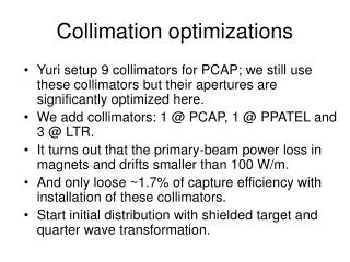
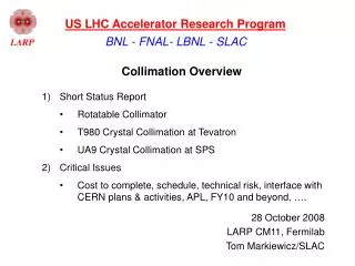
The LHC Collimation Challenge • A phased approach proposed and approved in 2003: • Phase 1 implements for the startup 4-stage cleaning and collimators optimized for maximum robustness (can take full Tevatron beam without damage). Confirmed by performance. • Phase 2 later implements solution for nominal and ultimate intensity. LHC quench limits: 5-30 mJ/cm3 360 MJ Collimators must clean unavoidable losses and survive expected beam loss… A. Rossi for the CERN collimation team
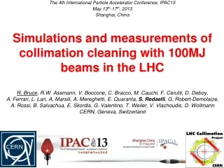
Loss Map at 1.18TeV Energy (Coll – Ph 1) Measured loss map at 1.18TeV for Beam 1 (ramp of December 8th 2009) Simulated proton loss map at 1TeV for Beam 1 *note that shower development is not included, only primary proton losses. LHC Beam Workshop
Collimation Phase 2 as complement to Phase 1 • Additional secondary collimators and scrapers in the IR3 and IR7 warm regions (already prepared): Cu jaws with higher stopping power and lower impedance • CERN white paper • SLAC – LARP • EuCARD • Collimators into super-conducting dispersion suppressors (cryo-collimators) in IR7, IR3 and IR2 • EuCARD (cryo-coll) • Combined Betatron/MomentumCleaning in IR3 Betatron Momentum A. Rossi for the CERN collimation team
Collimation • Cleaning inefficiency: • Intensity: Total no. of particles withnormalised amplitude > Ain Ds Total no. of particles undergoing inelastic interactions Quench limit Beam lifetime Rq = 7.0 × 10⁸/p/m/s at 450GeV Rq = 7.8 × 10⁶/p/m/s at 7 TeV hc = 7.8 × 10⁻⁴/m at 450GeV (for 0.1h and 3.2 × 10¹⁴ p) hc = 1.74 × 10⁻⁵/m at 7 TeV (for 0.1h and 3.2 × 10¹⁴ p) A. Rossi for the CERN collimation team
Downstream of IR7 b-cleaning Halo Loss Map Losses of off-momentum protons from single-diffractive scattering in TCP halo cryo-collimators Upgrade Scenario NEW concept transversely shifted by 3 cm without new magnets and civil engineering halo -3 m shifted in s +3 m shifted in s
99.997 %/m 99.99992 %/m Proton losses phase II: Zoom into DS downstream of IR7 quench level Very low load on SC magnets less radiation damage, much longer lifetime. T. Weiler Impact pattern on cryogenic collimator 2 Impact pattern on cryogenic collimator 1 Cryo-collimators can be one-sided! Th. Weiler, Conceptual Design Review Phase II, CERN April 2009
Minimized Plan: First IR3 or IR7? • If only one IR can be upgraded with cryogenic collimation in 2012, then we prefer IR3 to be done first. Why: • IR3 can be used to implement a combined betatron and momentum cleaning system (memo R. Assmann in 7/2008). • While we lose efficiency with the combined system, we win with the collimators in the cryogenic dispersion suppressors. Maybe we can get already nominal (simulations ongoing)… • SC link cable in IR3 OK for 500 kW losses at primary collimators (nominal). Maybe require additional passive absorbers. • LHC collimation with 28 collimators less than now faster setup and less beam time required. Lower impedance (20 TCP/TCS instead of 38 TCP/TCS)! • Limitations with Single Event Upset in IR7 are avoided as losses are relocated to IR3 (100 times less radiation to electronics for same beam loss in IR3). • System in IR7 kept operational in case of problems (spare system). • Much better flexibility to react to limitations. R. Assmann, CERN
Combined Momentum/Betatron Cleaning Local inefficiency hc (1/m) 100 10-1 10-2 10-3 10-4 10-5 Proton beam loss maps, showing local cleaning inefficiency (leakage) around the ring for horizontal (top) and vertical (bottom) cleaning with a combined IR3 system. A quench level is indicated for nominal LHC intensity and nominal peak loss rate (0.1%/s) The blue lines indicate losses in super-conducting magnets. IP3 IP5 0 5 10 15 20 25 (km) Simulations ongoing to see if we can go to nominal intensity 0 5 10 15 20 25 (km) Results from Th. Weiler studies PAC ‘09
Collimator impedance E. Metral, Conceptual Design Review LHC Phase 2 Collimation, CERN April ‘02
Energy deposition studiesfor Phase 2 collimators supporting the mechanical integration of prototypes, e.g. of the Phase II Rotatable Jaw design, developed by SLAC in the framework of the LARP collaboration between CERN and several laboratories in the USA 93 cm long Glidcop rotating jaws (J. Smith et al. EPAC ‘08) B Sec. AA B W – 1 h beam lifetime ~20 cm Sec. BB A A by the CERN FLUKA team L. Lari et al. EPAC ‘08
SLAC (LARP collaboration)Trapped Mode Analysis • Longitudinal TM • Transverse TM • Heating Analysis Vacuum tank is made of stainless steel (sigma=0.116e7s/m); Jaws and EM foils are made of copper (sigma=5.8e7s/m) L. Xiao (SLAC), presented at the Collimation Study Group, CERN 1/03/2010
Merlin – a viable tool for LHC collimator studies • Who:Roger Barlow and Adina Toader (Manchester University), Rob Appleby (CERN), Hywel Owen, James Molson (PhD) • Why Merlin – by Nick Walker (DESY) :Its c++ design makes it easy to extend and easy to add or modify behaviour and features of particles and components • Wakefields effects already implemented • Work on going: • Finish implementing scattering in collimators and benchmark against existing used codes for LHC collimation (add SD and Rutherford Scattering) • Improve Merlin speed. • Study the particle losses due to both scattering and wakefield effects. • Study different materials. Bunch (7TeV) emittance growthvsturn No: w/o (purple) and with wakefield A. Toader, 2nd EuCARD/ColMat WP meeting - March 22, 2010 at CERN
Collimation Backgrounds at LHC and CLIC • Lawrence Deacon, Grahame Blair, John Adams Institute @ RHUL • G4 studies : • Primary particles from halo distribution file fired into first betatron collimation spoiler • All particles above cut-off threshold (energy needed to penetrate iron wall) tracked to IP • Input spoiler hits from SixTrack (Adriana Rossi), 3.5 TeV beam • Energy loss maps, to be compare with beam loss monitors data • Would like to develop G4 models of beam loss monitors • Seeing particles reaching IP, need to generate more events and increase statistics L. Deacon, 2nd EuCARD/ColMat WP meeting - March 22, 2010 at CERN
CLIC studies: Muon Production e+ e- → μ+ μ- Pions γ→μ+ μ- e+ e- → μ+ μ- , e incident Lawrence Deacon, Grahame Blair, John Adams Institute @ RHUL
FNAL (LARP collaboration)Hollow electron beam collimator • Cylindrical, hollow, magnetically conned, pulsed electron beam overlapping with halo and leaving core unperturbed • Modeling: • 2D and 3D kick maps from measured distributions • performance vs lattice parameters • effect of misalignments, field-line ripple, bends G. Stancari (Fermilab), presented at the Collimation Study Group, CERN 15/03/2010
Summary and conclusions • CERN SixTracksimulations: • LHC Phase 1 collimation has been qualitatively confirmed by measurements at 1.18 TeV. Simulations at 450 GeV and 3.5 TeV beam to be compared to data are in progress. • LHC Phase 2 Combined Betatron/Momentum Cleaning in IR3 and cryo-collimators: simulations are on going to see if we can go to nominal intensity. • CERN Impedance simulations being refined and tune shift based measurements are foreseen as benchmark. • CERN FLUKA simulations to support design: • Energy deposition onto collimators. • Radiation to equipment. • Manchester University Merlin simulations: • Wakefield effect included. • Study different materials (including composites). • John Adams Institute G4 simulations: • Collimation Backgrounds at LHC and CLIC. • Machine imperfections are being included. Support in choosing materials and length A. Rossi for the CERN collimation team