Download
1 / 27
270 likes | 497 Vues
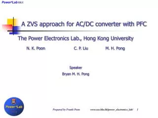
Power e Lab HKU. Power e Lab HKU. A ZVS approach for AC/DC converter with PFC. The Power Electronics Lab., Hong Kong University N. K. Poon C. P. Liu M. H. Pong Speaker Bryan M. H. Pong. Prepared by Franki Poon www.eee.hku.hk/power_electronics_lab/ 1. Load. Power e Lab HKU.

E N D
PowereLabHKU Power eLab HKU A ZVS approach for AC/DC converter with PFC The Power Electronics Lab., Hong Kong University N. K. Poon C. P. Liu M. H. Pong Speaker Bryan M. H. Pong Prepared by Franki Poon www.eee.hku.hk/power_electronics_lab/ 1
Load Power eLab HKU Some basic concepts • Input rectifiers and capacitor produce Pulsating input current • Harmonic currents are generated Prepared by Franki Poon www.eee.hku.hk/power_electronics_lab/ 2
Ipfc Idc Power eLab HKU A conventional method • A boost converter and a DC/DC converter Prepared by Franki Poon www.eee.hku.hk/power_electronics_lab/ 3
Ipfc Idc Power eLab HKU A popular method among researchers • Single stage design which combines the boost and the DCDC converters Prepared by Franki Poon www.eee.hku.hk/power_electronics_lab/ 4
Power eLab HKU Is single stage design always better? Let us take a look Prepared by Franki Poon www.eee.hku.hk/power_electronics_lab/ 5
Ipfc Idc Power eLab HKU Why two-stage design? • Advantage • Losses Ipfc2 + Idc2 • Fix DCDC input voltage • Controllable bulk voltage • Disadvantage • Need two controllers • One more MOSFET Prepared by Franki Poon www.eee.hku.hk/power_electronics_lab/ 6
Ipfc Idc Power eLab HKU Why single-stage design? • Advantage • One controller • One MOSFET less • Disadvantage • Losses (Ipfc + Idc)2 • High Idcat low line • Higher Ipfc • High current stress • High voltage stress Prepared by Franki Poon www.eee.hku.hk/power_electronics_lab/ 7
Power eLab HKU Good reasons for two-stage • Two-Stage • Advantages • Losses Ipfc2 + Idc2 • Fix DCDC input voltage • Controllable bulk voltage • Disadvantages • Need two controller • One more MOSFET • Single Stage • Advantages • One controller • One MOSFET less • Disadvantages • Losses (Ipfc + Idc)2 • High Idcat low line • Higher Ipfc • High current stress • High voltage stress Prepared by Franki Poon www.eee.hku.hk/power_electronics_lab/ 8
Power eLab HKU Our new idea Boost + Asymmetric half-bridge with soft switching DMpfc > DM2 M1 Mpfc M2 Prepared by Franki Poon www.eee.hku.hk/power_electronics_lab/ 9
Power eLab HKU Zero voltage state - M2 M1turn off then . . Prepared by Franki Poon www.eee.hku.hk/power_electronics_lab/ 10
Power eLab HKU Zero voltage state - Mpfc After M2turn on Prepared by Franki Poon www.eee.hku.hk/power_electronics_lab/ 11
Power eLab HKU Two separate converters M2turn on Mpfcturn on Prepared by Franki Poon www.eee.hku.hk/power_electronics_lab/ 12
Power eLab HKU Zero voltage state – M1 M2turn off Mpfcturn on Prepared by Franki Poon www.eee.hku.hk/power_electronics_lab/ 13
Power eLab HKU One cycle on asymmetric M1turn on Mpfcturn on Prepared by Franki Poon www.eee.hku.hk/power_electronics_lab/ 14
Power eLab HKU One cycle on PFC M1turn on Mpfcturn off Prepared by Franki Poon www.eee.hku.hk/power_electronics_lab/ 15
Power eLab HKU It’s great, but . . . If DMpfc < DM2 DMpfc =DM2 No control for PFC !! Prepared by Franki Poon www.eee.hku.hk/power_electronics_lab/ 16
Power eLab HKU After all – small Maux added For all DMpfcand all DM2 M1 Maux Mpfc M2 Prepared by Franki Poon www.eee.hku.hk/power_electronics_lab/ 17
Power eLab HKU Final timing arrangement ZVS too M2 gate drive A M1 gate drive B Maux gate drive Mpfc gate drive VA = VB VMaux_ds = VA-VB =0 Prepared by Franki Poon www.eee.hku.hk/power_electronics_lab/ 18
Power eLab HKU Practical consideration M1 Maux Mpfc Doff M2 guarantee a path for Laux current when M2 off at any time Prepared by Franki Poon www.eee.hku.hk/power_electronics_lab/ 19
Power eLab HKU Practical circuit – O/P 12V@10A 250uH IRF840A Two diodes are used to clamp ringing STD5NM50 12uH 8uH STPS12NM50 STPS12NM50 Active Diode Prepared by Franki Poon www.eee.hku.hk/power_electronics_lab/ 20
Power eLab HKU Simplified timing circuit L5991 M2 gate O/P Sync M1 gate Maux gate Sync L4981 Mpfc gate O/P Prepared by Franki Poon www.eee.hku.hk/power_electronics_lab/ 21
Power eLab HKU How does it look? A 120W, 12V10A AC adapter Width = 12.6cm Depth = 6.3cm Height = 1.9cm Prepared by Franki Poon www.eee.hku.hk/power_electronics_lab/ 22
Power eLab HKU ZVS on M2 Prepared by Franki Poon www.eee.hku.hk/power_electronics_lab/ 23
Power eLab HKU ZVS on Mpfc Prepared by Franki Poon www.eee.hku.hk/power_electronics_lab/ 24
Power eLab HKU ZVS on Mpfc & M2 Prepared by Franki Poon www.eee.hku.hk/power_electronics_lab/ 25
Power eLab HKU Losses and Efficiency < 1W at no load 91% efficiency 12V@10A Prepared by Franki Poon www.eee.hku.hk/power_electronics_lab/ 26
Power eLab HKU Finally . . . • Simple Boost + Asymmetric Half-bridge configuration – Good Combination. • All ZVS behaviors – Very little added cost. • Two separate converter – Easy to control • Active diode can be incorporated – <1W no load power • Simple PWM controller – simple ASIC Prepared by Franki Poon www.eee.hku.hk/power_electronics_lab/ 27