Download
1 / 14
160 likes | 391 Vues
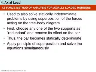
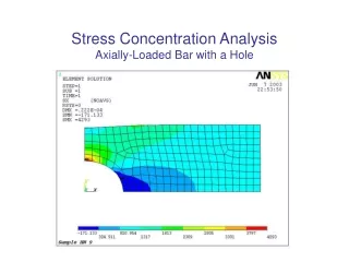
WORKSHEET 7 AXIALLY LOADED MEMBERS. Q1. Are tension structures or compression structures more efficient when loaded axially ?. tension structures . Q2. why ?. tension structures are not subject to buckling they pull straight - can use thin cables can use: stress = Force / Area.

E N D
Q1 Are tension structures or compression structures more efficient when loaded axially ? tension structures Q2 why ? tension structures are not subject to buckling they pull straight - can use thin cables can use: stress = Force / Area
Q3 What is meant by: (a) a short column a column which will fail in true compression (b) a long column a column which buckles before full compressive strength is reached
Q4 What affects the buckling load (or buckling stress)? (a) the slenderness ratio - l/r (or l/B rect. sections) the slenderness ratio takes into account the effective length, l and the stiffness (radius of gyration) of the X-section r = (I/A) buckling load inversely proportional to slenderness ratio i.e. greater the slenderness ratio - more will tend to buckle (b) the modulus of elasticity, E materials with higher E will buckle less (c) end fixing conditions - restraints but included in slenderness ratio - effective length free end Eff Length = 2 x l, fixed ends Eff Length = 0.5 x l
Q5 What are good sections for columns? (i) sections which have similar radii of gyration in all directions (ii) sections in which the major part of the material is a far from the Centre of Gravity as possible Q6 Why? (i) so that they do not buckle in a weak directions (ii) to use the material efficiently
Q7 What are two effects which can cause a pier to overturn? (a) a horizontal load (b) an eccentric vertical load
Q8 What is the middle-third rule? the middle-third rule tells you that as long as the resultant reaction falls in the middle-third of the base of the pier then no tension will develop in the pier. if the middle-third rule holds the pier will not lift off its base there will be a factor of safety of >3 if the middle-third rule holds
300 1000 8kN 1kN Pier 600 x 600mm X R=9 h stress = P/A ±Pe/Z Z = bd2/6 Q9 (a) The diagram shows a heavy steel gate hung from a hollow brick pier which weighs 8kN. Investigate the stability of the pier. (a) assume the pier is sitting on (but not stuck to) a strong concrete footing. take moments about the point X (i) will the pier overturn? No Overturning Moment (clockwise): M =1 x 1 = 1 kNm Potential Stabilizing Moment (anticlockwise): M =8 x 0.3 = 2.4 kNm (ii) what is the margin of safety? 2.4:1 OTM can increase up to 2.4kNm before overturning occurs
Q9 (b) (b) where is the resultant of the two loads? 155.6mm from X 144.4mm from centre 1 x 1000 + R x h = 8 x 300 9 x h = 2400 -1000 h = 1400 / 9 = 155.6 (i) is it within the middle third of the base? No (ii) is this what you would expect from (a)? In (a) we assumed that there would be no crushing of the leading edge of the pier. Under this condition the middle-third rule gives a factor of safety of >3. For a factor of safety of 2.4 we would expect the reaction to be just outside the middle-third
Q9 (c) (c) calculate the stress distribution under the pier stress = P/A (compressive part) ± M/Z (bending part) M = P x e = 1 x 1300 (or 9 x 144.4) = 1300kNmm Z = bd2/6 = 600 x 6002 / 6 = 36 x 106 mm3 stress = 9000 / (600 x 600) ± 1300000 / 36 x 106 = 0.025 ± 0.036 MPa (i) is it trying to develop tension on one side? yes on the gate side the stress is 0.061 MPa (61kPa) - compression on the other side it would be -0.011 MPa (11kPa) (tension) since the interface cannot develop tension, a redistribution would occur a different analysis is required to find that the maximum compressive stress would increase to 0.096 MPa (ii) is this what you would expect from (b)? yes since the reaction is outside the middle third you would expect tension to tend to develop
Q9 (d) (d) if you make the pier solid, it will be about twice as heavy. Will this make it safer against overturning? yes The potential stabilising moment would double while the overturning moment remains the same. No tension would develop (the reaction would be within the middle third) and it would be safer against overturning
self weight 115 115 wind 0.5kPa 1200mm 600 A R = weight h x = 115-h Q10(a) A freestanding garden wall is 230mm thick and 1200mm high. The density of brick is 19kN/m3. The wind load in this location is 0.5 kPa (a) Find the location of the reaction on the base weight of wall (of length 1m) = 1.2 x 0.23 x 1 x 19 = 5.244 kN wind load on 1m length of wall = 0.5 x 1 x 1.2 = 0.6 kN taking moments about A: overturning moment = 0.6 x 600 = 360 kNmm restraining moment = 5.244 x 115 = 603.1 kNmm 5.244 x h + 360 = 603.1 h = 243.1/5.244 = 46.4 mm (i) is it within the base? yes (i) is it within the middle third? no the reaction is 115 - 46.4 = 68.6mm from the centre of the wall. the middle third is 38.3mm from the centre of the wall. so the reaction is well outside the middle third.
self weight 115 115 wind 0.5kPa 1200mm A 5.244kN 600 R = weight h x 0.6kN x Q10(a) A freestanding garden wall is 230mm thick and 1200mm high. The density of brick is 19kN/m3. The wind load in this location is 0.5 kPa (a) Find the location of the reaction on the base weight of wall (of length 1m) = 1.2 x 0.23 x 1 x 19 = 5.244kN wind load on 1m length of wall = 0.5 x 1 x 1.2 = 0.6kN GRAPHICAL METHOD X/600 = 0.6 / 5.244 X = 0.6 x 600 / 5.244 X = 68.6 the reaction is 68.6mm from the centre of the wall.
5.44kN 2 x 68.6 68.6 6 x 68.6 Q10(b, c) (b) How wide would the footing have to be to bring the reaction within the middle third? Forgetting the weight and depth of the footing, width of footing would have to be 6 x 68.6 = = 412mm We would probably make it 450mm wide. This is the width of a common backhoe bucket. (c) What other options are there for increasing the stability of the wall? (i) put a heavy coping on top (has to be wide rather than high otherwise subject to wind) (ii) make the wall thicker (expensive) (iii) attached piers (iv) zigzag plan (similar to (iii) but more interesting