Download
1 / 10
100 likes | 231 Vues
The document outlines the specifications and design of the Synchronization & Control Board (SCB) for RPC electronics, emphasizing its integration with the Front-End (FE) board. It details power consumption metrics, communication channels, HV and LV distribution requirements, and monitoring of digital parameters. Key milestones are provided for the development and testing phases of the FE chip and related electronics. The system is designed for fault tolerance and is capable of supporting multiple channels for efficient operation within the RPC framework.

E N D
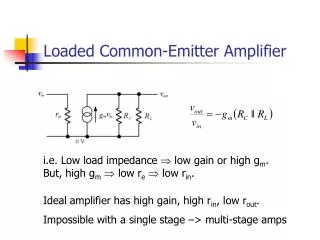
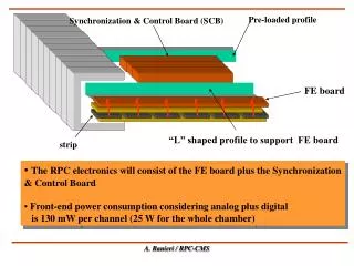
Pre-loaded profile Synchronization & Control Board (SCB) FE board “L” shaped profile to support FE board strip • The RPC electronics will consist of the FE board plus the Synchronization & Control Board • Front-end power consumption considering analog plus digital • is 130 mW per channel (25 W for the whole chamber) A. Ranieri / RPC-CMS
12 flat cables per station from FEB to SCB “L” shaped profile to support FE board FE board Optical link LB Clock line SCB Synchronization & Control Board (1 or 2/layer) DCS line SCB Data Line
FE Board Layout 8 8 FEC+DAC test point FEC+DAC test point DAC DAC Voltage Regul Voltage Regul FEC FEC 4 4 4 LVDS-R LVDS-R LVDS-R 16 LVDS output DCS from SCB A. Ranieri / RPC-CMS
Synchronization & Control Board (SCB) Channel Link (x6) Twin Coax To LB Synchro & FIFO CDC 509 Ck1 96 LVDS-R (x 24) Signal In from FEC Synchro & FIFO CDC 509 DLL MCK from LB Ck2 48 LVDS-D (x 12) Test Out from FIFO Synchro & FIFO CDC 509 TS 24 DCS Bus LVDS-D (x 6) DCS chip set DCS out for DAC A. Ranieri / RPC-CMS
HV System requirements • Maximum number of HV channels ~ 4000 • Max value = 12.000 V • Imax = .5 mA/channel • Magnetic field inside ironB = 1.8 Tesla • Possibility to switch off one sub-channel only • Single rate counting for each sub-channel: (desirable) • Rad-hard devices necessary ? (not necessary for RPC) • Fault tolerant system (redundancy): (desirable) • HV & LV system crates on the balcony around the detector RPC_CMS HV & LV Distribution A. Ranieri / RPC-CMS
RPC sector in the Barrel LV analog LV digital 4 LV Ch. MB4 96 channels 96 channels 8 HV Ch. 4 LV Ch. MB3 8 HV Ch. 96 channels 96 channels 96 channels + 96 channels MB2 8 HV Ch. 4 LV Ch. 96 channels + 96 channels LV Channel HV Channel 96 channels + 96 channels MB1 8 HV Ch. 4 LV Ch. 96 channels + 96 channels 12 groups of 96 channels to be powered to LV, grouped into 16 LV channels Current absorption : .5 mA / HV Channel RPC_CMS HV & LV Distribution A. Ranieri
HV SY1527 possible segmentation 8 Ch RDB 1 SY1527 1 Crate/4 RPC sectors Ch. 1 (2 slot) (HV) Ch. 2 8 Ch Ch. 3 RDB 2 Ch. 4 Ch. 5 RDB=Remote Distribution Board Ch. 6 Ch. 7 8 Ch Ch. 8 8 Ch (HV) In the ipothesys of 12KV/sub-channel
HV SY1527 possible segmentation for HV & LV (Barrel case) • Considering: • 16 sub-channels (2 RDB - 8 ) / 2 HV slot • 16 sub-channels x 0.5 mA = 8 mA • 8 x 8 mA x 12 KV = 768 W/crate/ 4 sectors • 60 sectors : 4 = total of 15 SY1527 for HV only • 25 W x 12 = 300 W/ sector • 300 W x 60 = 18000 W : 2000 W = 9 SY1527 for LV only RPC_CMS HV Distribution A. Ranieri
Number of parameters to be controlled • 2000 digital words to be monitored as threshold values for a total of 13000 FE Boards for the entire detector (assuming to have only one threshold value for a group of 6 boards) • pulse width coming from the discriminator, fixed at 100 ns • number of temperature sensor = 1 / SCB (1/RPC layer) • Dead Channels: implementation of a digital mask on the synchronizer, to switch off dead channels RPC_CMS Calibration & Monitoring
RPC FE Electronics milestones • NewFE chip prototype: end of March 99 • chip test on new FE board(LAB): end of March 99 • chip pre-production: May 99 • test of chip pre-production: June 99 • new FE board pre-production & mounting: June-July 99 • test at CERN: July-September 99 • final production of FE: June 2000 • SCB prototype development: October 99 RPC FE Milestones