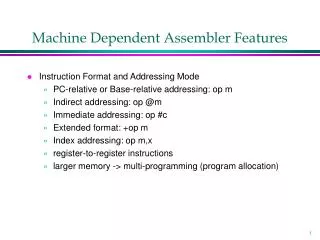
Machine Independent Assembler Features: Program Blocks and Linking Techniques
This chapter discusses the features of machine-independent assemblers, focusing on program blocks, control sessions, and linking techniques. Program blocks group related code and data, optimizing memory usage and execution time. The assembler logically rearranges segments to create these blocks, enabling improved readability and code sharing. It also details the processing during assembly passes, particularly how labels are assigned addresses relative to blocks. The concept of control sections is introduced, allowing independent loading and relocation, with an emphasis on managing external references between sections.

Machine Independent Assembler Features: Program Blocks and Linking Techniques
E N D
Presentation Transcript
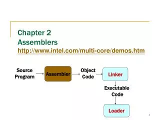
Chapter 8 :Machine Independent Assembler Features (Program blocks, Control Session and Linking)
Program Blocks • Collect many pieces of code/data that scatter in the source program but have the same kind into a single block in the generated object program. • For example, code block, initialized data block, un-initialized data block. (Like code, data segments on a Pentium PC). • Advantage: • Because pieces of code are closer to each other now, format 4 can be replaced with format 3, saving space and execution time. • Code sharing and data protection can better be done. • With this function, in the source program, the programmer can put related code and data near each other for better readability.
Program Block Example There is a default block.
Use the default block. The default block (unnamed) contains the executable instructions. The CDATA block contains all data areas that are a few words or less. The CBLKS block contain all data areas that consist of large blocks of memory.
Assembler’s Job • A program block may contain several separate segments of the source program. • The assembler will (logically) rearrange these segments to gather together the pieces of each block. • These blocks will then be assigned addresses in the object program, with the blocks appearing in the same order in which they were first begun in the source program. • The result is the same as if the programmer had physically rearranged the source statements to group together all the source lines belonging to each block.
Assembler’s Processing • Pass 1: • Maintain a separate location counter for each program block. • The location counter for a block is initialized to 0 when the block is first begun. • The current value of this location counter is saved when switching to another block, and the saved value is restored when resuming a previous block. • Thus, during pass 1, each label is assigned an address that is relative to the beginning of the block that contains it. • After pass 1, the latest value of the location counter for each block indicates the length of that block. • The assembler then can assign to each block a starting address in the object program.
Assembler’s Processing • Pass 2 • When generating object code, the assembler needs the address for each symbol relative to the start of the object program (not the start of an individual problem block) • This can be easily done by adding the location of the symbol (relative to the start of its block) to the assigned block starting address.
Example Program Loc/Block
There is no block number for MAXLEN. This is because MAXLEN is an absolute symbol.
Code Generation in Pass 2 • 20 0006 0 LDA LENGTH 032060 • The SYMTAB shows that LENGTH has a relative address 0003 within problem block 1 (CDATA). • The starting address for CDATA is 0066. • Thus the desired target address is 0066 + 0003 = 0069. • Because this instruction is assembled using program counter-relative addressing, and PC will be 0009 when the instruction is executed (the starting address for the default block is 0), the displacement is 0069 – 0009 = 60.
Advantages • Because the large buffer area is moved to the end of the object program, we no longer need to use format 4 instructions on line 15, 35, and 65. • For the same reason, use of the base register is no longer necessary; the LDB and BASE have been deleted. • Code sharing and data protection can be more easily achieved.
Object Code Layout • Although the assembler internally rearranges code and data to form blocks, the generated code and data need not be physically rearranged. The assembler can simple write the object code as it is generated during pass 2 and insert the proper load address in each text record.
Leave the Job to Loader No code need to be generated for these two blocks. We just need to reserve space for them.
Control Section • A control section is a part of the program that maintains its identity after assembly. • Each such control section can be loaded and relocated independently of the others. (Main advantage) • Different control sections are often used for subroutines or other logical subdivisions of a program. • The programmer can assemble, load, and manipulate each of these control sections separately.
Program Linking • Instructions in one control section may need to refer to instructions or data located in another control section. (Like external variables used in C language) • Thus, program (actually, control section) linking is necessary. • Because control sections are independently loaded and relocated, the assembler is unable to know a symbol’s address at assembly time. This job can only be delayed and performed by the loader. • We call the references that are between control sections “external references”. • The assembler generates information for each external reference that will allow the loader to perform the required linking.
Control Section Example Default control section
External References • Symbols that are defined in one control section cannot be used directly by another control section. • They must be identified as external references for the loader to handle. • Two assembler directives are used: • EXTDEF (external definition) • Identify those symbols that are defined in this control section and can be used in other control sections. • Control section names are automatically considered as external symbols. • EXTREF (external reference) • Identify those symbols that are used in this control section but defined in other control sections.
Code Involving External Reference (1) • 15 0003 CLOOP +JSUB RDREC 4B100000 • The operand (RDREC) is named in the EXTREF statement, therefore this is an external reference. • Because the assembler has no idea where the control section containing RDREC will be loaded, it cannot assemble the address for this instruction. • Therefore, it inserts an address of zero. • Because the RDREC has no predictable relationship to anything in this control section, relative addressing cannot be used. • Instead, an extended format instruction must be used. • This is true of any instruction whose operand involves an external reference.
Code Involving External Reference (2) • 160 0017 +STCH BUFFER,X 57900000 • This instruction makes an external reference to BUFFER. • The instruction is thus assembled using extended format with an address of zero. • The x bit is set to 1 to indicate indexed addressing.
Code Involving External Reference (3) • 190 0028 MAXLEN WORD BUFEND – BUFFER 000000 • The value of the data word to be generated is specified by an expression involving two external references. • As such, the assembler stores this value as zero. • When the program is loaded, the loader will add to this data area the address of BUFEND and subtract from it the address of BUFFER, which then results in the desired value. • Notice the difference between line 190 and 107. In line 107, EQU can be used because BUFEND and BUFFER are defined in the same control section and thus their difference can be immediately calculated by the assembler.
External Reference Processing • The assembler must remember (via entries in SYMTAB) in which control section a symbol is defined. • Any attempt to refer to a symbol in another control section must be flagged as an error unless the symbol is identified (via EXTREF) as an external reference. • The assembler must allow the same symbol to be used in different control sections. • E.g., the conflicting definitions of MAXLEN on line 107 and 190 should be allowed.
Two New Record Types • We need two new record types in the object program and a change in the previous defined modification record type. • Define record • Give information about external symbols that are defined in this control section • Refer record • List symbols that are used as external references by this control section.
Program Relocation • The modified “modification record” can still be used for program relocation. Program name
More Restriction on Expression • Previously we required that all of the relative terms in an expression be paired to make the expression an absolute expression. • With control sections, the above requirement is not enough. • We must require that both terms in each pair must be relative within the same control section. • E.g.1. BUFEND- BUFFER (allowed) because they are defined in the same control section. • E.g.2. RDRED – COPY (not allowed) because the value is unpredictable. • Otherwise, the expression is a relative expression and the unresolved terms must be handled by the loader using the modification records.